Yaskawa VS-616G5 Series Revision F Programming Manual User Manual
Page 79
VS-616G5 Programming Manual
79
V/f
V/f w/PG Open Loop
Vector
Flux
Vector
It is possible to mix analog and digital references in the multi-speed input function. The parameters
must be set as shown below
.
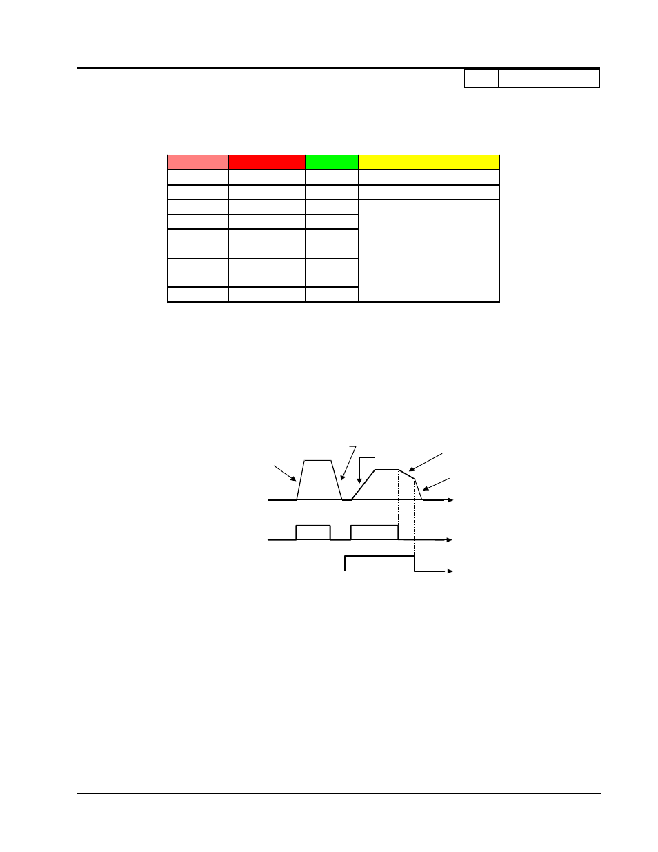
· Multi Accel/Dec1 (Set value = 7)
Open: Acceleration 1 / Deceleration 1 is set by parameters C1-01and C1-02 respectively.
Closed: Acceleration 2 / Deceleration 2 is set by parameters C1-03 and C1-04 respectively.
· External Baseblock N.O. (setting: “8”)
Baseblock operation is performed when the contact output is closed. External baseblock operation
differs as described below, depending on the run command input status.
When an external baseblock signal is input while the inverter is running, BB blinks on the digital
operator display, and the inverter output is shut OFF. When the external baseblock signal is
removed, operation restarts at the previous frequency reference before baseblock. Output voltage is
then increased up to its previous level before baseblock, in the voltage recovery time (L2-04).
When a stop signal is input and an external baseblock signal is input while the inverter is decelerat-
ing, BB blinks on the digital operator, the inverter output shuts OFF and the frequency reference is
set to 0.
P a r a m e te r
R e fe rence
Digita l
Ana log
(d1-01)
Reference 1
b1-01 = 0 b1-01 = 1 (terminal 13 or 14)
(d1-02)
Reference 2
H3-05
≠
0 H3-05 = 0 (terminal 16)
(d1-03)
Reference 3
d1-03
(d1-04)
Reference 4
d1-04
(d1-05)
Reference 5
d1-05
(d1-06)
Reference 6
d1-06
not available
(d1-07)
Reference 7
d1-07
(d1-08)
Reference 8
d1-08
(d1-09)
Jog Reference
d1-09
Accel Tim e 1
(C1-01)
Decel Tim e 1
(C1-02)
Accel Tim e 2
(C1-03)
Decel Tim e 2
(C1-04)
Decel Tim e 1
(C1-02)
Output
Frequency
F W D ( R E V )
R u n C o m m a n d
Accel/Decel
Tim e S e lection
(Term inals 3 to 8)
t
t
t
Section H: Control Circuit Terminals
H1 Digital Inputs