Yaskawa VS-616G5 Series Revision F Programming Manual User Manual
Page 61
VS-616G5 Programming Manual
61
V/f
V/f w/PG Open Loop
Vector
Flux
Vector
E3
Motor 2 Set-up
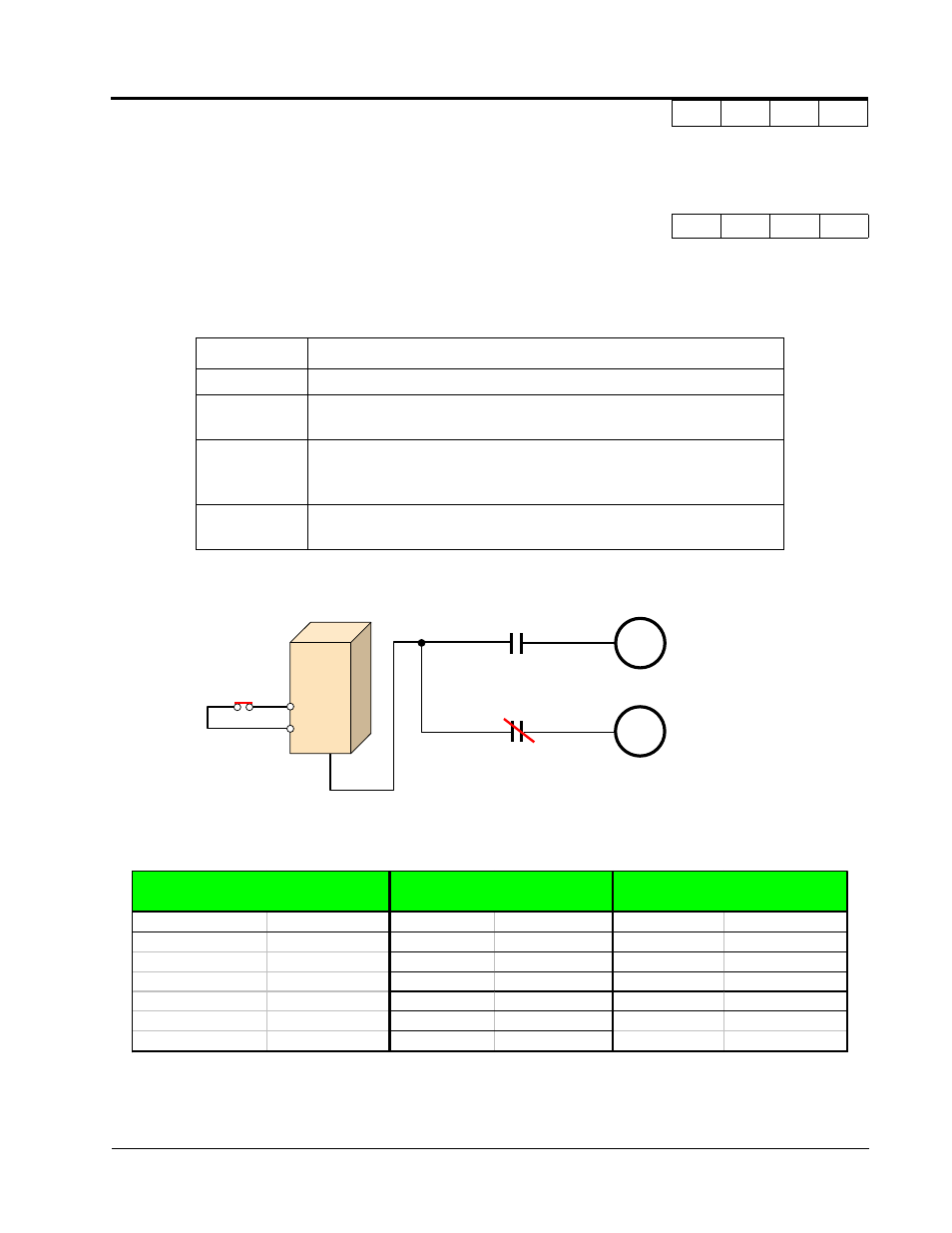
The G5 inverter has the capability to control 2 motors independently. A second motor may be selected
using a multi-function contact input.
Select the control method best suited for your application for Motor 2.
The following is a list of parameters that become effective when motor 2 is selected.
The inverter must be stopped to switch motors.
E3-01 Motor 2 Control Method Selection
Control Method
A
A
A
A
Setting
Description
0
V/f Control - For general-purpose and multiple motor applications.
1
V/f with PG Feedback - For general-purpose applications requiring closed
loop speed control.
2
Open Loop Vector (factory default) - For applications requiring precise
speed control, quick response and higher torque at low speeds (150%
torque below 1Hz).
3
Flux Vector - For applications requiring very precise speed and torque con-
trol at a wide speed range including 0 speed. Uses encoder feedback.
G5
M
M
Motor 1
Motor 2
Function E3
Function E4
Function E5
Control Method 2
V/F Pattern 2
Motor Setup 2
E3-01
Control Method 2 E4-01
Max Frequency E5-01
Motor Rated FLA
E4-02
Max Voltage
E5-02
Motor Rated Slip
E4-03
Base Frequency E5-03
No-Load Current
E4-04
Mid Frequency
E5-05
Term Resistance
E4-05
Mid Voltage
E5-06
Leak Inductance
E4-06
Min Frequency
E4-07
Min Voltage
Section E: Motor Parameters
E3 Motor 2 Set-up