Yaskawa VS-616G5 Series Revision F Programming Manual User Manual
Page 80
V/f
V/f w/PG Open Loop
Vector
Flux
Vector
80
VS-616G5 Programming Manual
Section H: Control Circuit Terminals
H1 Digital Inputs
· External Baseblock N.C. (setting: “9”)
Baseblock operation is performed similar to setting “8”, except that operation is performed when the
contact output is closed.
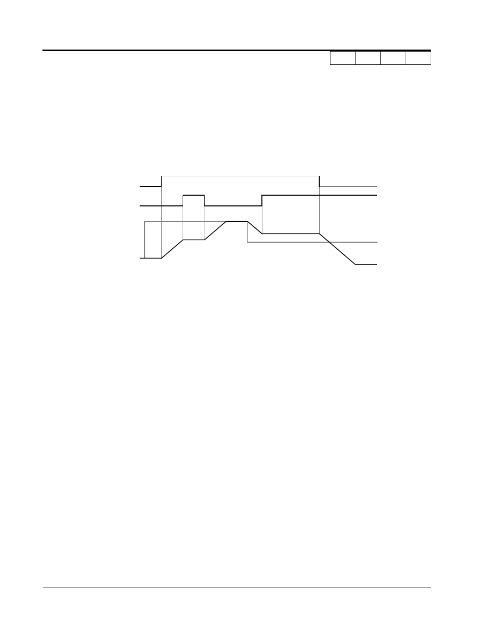
· Accel/Decel Hold Command (setting: “A”)
The accel/decel hold command is used to temporarily hold the output frequency at the current fre-
quency reference, when the hold command is input. When a stop command is input, the accel/decel
hold condition is released and operation stops.
Notes:
1. When hold reference memory selection is enabled (D4-01 = “1”) and an accel/decel
hold command is input, by inputting a run command again after a stop command is
input, the held output frequency is stored unless the accel/decel stop command is
released. Operation resumes at the stored frequency.
2. When the power supply is turned OFF after the accel/decel hold command is input, the
held output frequency is also stored.
3. When D4-01 is set to “0”. the held output frequency is not stored,
· Inverter Overheat OH2 Alarm (setting: “B”)
When the inverter overheat alarm signal is input, OH2 blinks on the digital operator display. This
contact can be connected to an external temperature switch for monitoring the inverter ambient tem-
perature. A multi-function contact output (H2-__) can be set to “20” to close a contact at this condi-
tion.
· Multi-function Analog Input Selection (setting: “C”)
This setting disables the terminal 16 multi-function analog input.
Open:
Terminal 16 command is not accepted.
Closed:
Terminal 16 command is accepted.
· Feedback Mode During V/f Selection (setting: “D”)
Feedback input can be disabled while the inverter is running when this function is selected. How-
ever, the speed control integral value (C5-05) is held until stop.
Open:
Feedback control enabled (closed loop)
Closed:
Feedback control disabled (open loop)
This function is available only during V/f control with PG feedback.
OFF
ON
OFF
ON
ON
OFF
OFF
Fwd Run
Accel/Decel
Output
Hold Command
Frequency
Figure 32 Accel/Decel Hold Command Timing Diagram
Frequency
Reference