Yaskawa VS-616G5 Series Revision F Programming Manual User Manual
Page 113
VS-616G5 Programming Manual
113
Selects whether a fault contact output is activated during automatic restart.
L6
Torque Detection
The overtorque detection circuit activates when the motor load causes the motor current (or torque dur-
ing vector control) to exceed the overtorque detection level (L6-02). When an overtorque condition is
detected, alarm signals are sent to multi-function output terminals 9, 25 and 26.
To output an overtorque detection signal, select torque detection 1 at either of the multi-function con-
tact outputs (H2-__ = “B” or “17”). Refer to section H2, Digital Outputs on page 88, for more details.
Activates overtorque detection, and selects whether detection generates an alarm or a fault.
L6-01 Notes:
1. To detect torque during acceleration or deceleration, set to “2” or “4”.
2. To continue operation after overtorque detection, set to “1” or “2”. During detection, the digital
operator displays an “OL3” alarm (blinking).
3. To stop the inverter after an overtorque detection fault, set to “3” or “4”. During detection, the dig-
ital operator displays an “OL3” fault.
L5-02 Automatic Restart Operation Selection
Restart Sel
B
B
B
B
Setting
Description
0
No fault relay (factory default)
1
Fault relay active
L6-01 Overtorque Detection 1 Selection
Torq Det 1 Sel
B
B
B
B
Setting
Description
0
Overtorque detection is disabled (factory default).
1
Overtorque detection is enabled whenever at the speed agree level (when inverter is not
accelerating or decelerating). Continue running after detection (OL3 alarm).
2
Overtorque detection is enabled always. Continue running after detection (OL3 alarm).
3
Overtorque detection is enabled whenever at the speed agree level. Coast to a stop after
detection (OL3 fault).
4
Overtorque detection is enabled always. Coast to a stop after detection (OL3 fault).
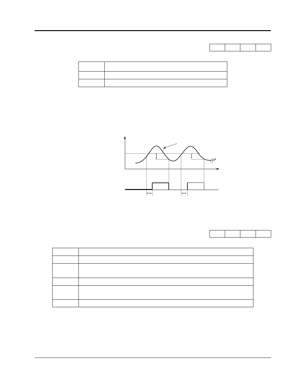
* Release width (hysteresis) during overtorque detection is 5% of the inverter rated current level.
Inverter Rated Current
L6-02
Time
ON
ON
L6-03
L6-03
Multi-function Contact
Output Signal
(Overtorque Detection Signal)
Terminal 9, 25, 26
*
*
Figure 55 Overtorque Characteristics Timing Diagram
Motor Current
Section L: Protection Parameters
L6 Torque Detection