Vs-616g5 standard connection diagram – Yaskawa VS-616G5 Series Revision F Quick-Start User Manual
Page 24
Advertising
24
VS-616G5 Installation & Quick-Start Manual
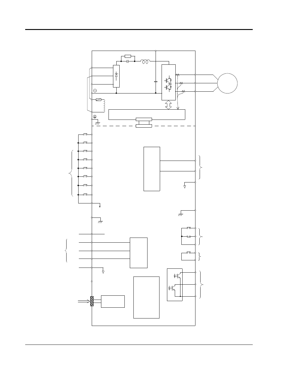
VS-616G5 Standard Connection Diagram
Figure 11 VS-616G5 Terminal Diagram - Model CIMR-G5U5110
Digital
RS-232
Serial Port
Analog Inputs
(250
Ω)
Operator
(10-pin)
IM
1 - Forward Run when CLOSED
2 - Reverse Run when CLOSED
3
11 (Com)
4
5
6
15
13
14
17
PWM
Multi-Function
Inputs
12
(+15V, 20mA)
(20k
Ω)
(0V)
-10 to +10V
4 to 20mA
-10 to +10V 23
(Com) 22
12
18
19
20
9
10
Multi-Function
Analog Outputs
A/D
±11 bit
Gate Drive
T1
T2
T3
L1
L2
L3
7
8
16 (20k
Ω)
-10 to +10V
-10 to +10V 21
33 (-15V, 20mA)
26
27
Multi-Function
PHC Outputs
48V, 50mA or less
25
⊕3
+
l
1
Fault Contact Outputs
250VAC, 1A or less
30VDC, 1A or less
Multi-Function
Contact Output
l
2
Chapter 1 - Receiving & Installation
Wiring
Advertising
See also other documents in the category Yaskawa Equipment:
- Tag Generator (30 pages)
- MP3300iec (82 pages)
- 1000 Hz High Frequency (18 pages)
- 1000 Series (7 pages)
- PS-A10LB (39 pages)
- iQpump Micro User Manual (300 pages)
- 1000 Series Drive Option - Digital Input (30 pages)
- 1000 Series Drive Option - CANopen (39 pages)
- 1000 Series Drive Option - Analog Monitor (27 pages)
- 1000 Series Drive Option - CANopen Technical Manual (37 pages)
- 1000 Series Drive Option - CC-Link (38 pages)
- 1000 Series Drive Option - CC-Link Technical Manual (36 pages)
- 1000 Series Drive Option - DeviceNet (37 pages)
- 1000 Series Drive Option - DeviceNet Technical Manual (81 pages)
- 1000 Series Drive Option - MECHATROLINK-II (32 pages)
- 1000 Series Drive Option - Digital Output (31 pages)
- 1000 Series Drive Option - MECHATROLINK-II Technical Manual (41 pages)
- 1000 Series Drive Option - Profibus-DP (35 pages)
- AC Drive 1000-Series Option PG-RT3 Motor (36 pages)
- Z1000U HVAC MATRIX Drive Quick Start (378 pages)
- 1000 Series Operator Mounting Kit NEMA Type 4X (20 pages)
- 1000 Series Drive Option - Profibus-DP Technical Manual (44 pages)
- CopyUnitManager (38 pages)
- 1000 Series Option - JVOP-182 Remote LED (58 pages)
- 1000 Series Option - PG-X3 Line Driver (31 pages)
- SI-EN3 Technical Manual (68 pages)
- JVOP-181 (22 pages)
- JVOP-181 USB Copy Unit (2 pages)
- SI-EN3 (54 pages)
- SI-ET3 (49 pages)
- MECHATROLINK-III (35 pages)
- EtherNet/IP (50 pages)
- SI-EM3 (51 pages)
- 1000-Series Option PG-E3 Motor Encoder Feedback (33 pages)
- 1000-Series Option SI-EP3 PROFINET (56 pages)
- PROFINET (62 pages)
- AC Drive 1000-Series Option PG-RT3 Motor (45 pages)
- SI-EP3 PROFINET Technical Manual (53 pages)
- A1000 Drive Option - BACnet MS/TP (48 pages)
- 120 Series I/O Modules (308 pages)
- A1000 12-Pulse (92 pages)
- A1000 Drive Software Technical Manual (16 pages)
- A1000 Quick Start (2 pages)
- JUNMA Series AC SERVOMOTOR (1 page)
- A1000 Option DI-101 120 Vac Digital Input Option (24 pages)