3 operation mode selection – Yaskawa VS-616G5 Series Revision F Quick-Start User Manual
Page 47
44
VS-616G5 Installation & Quick-Start Manual
2.3
OPERATION MODE SELECTION
The VS-616G5 has two operation modes: LOCAL and REMOTE (see table below for description). These two
modes can be selected by the digital operator “LOCAL/REMOTE” key or a multi-function input terminal com-
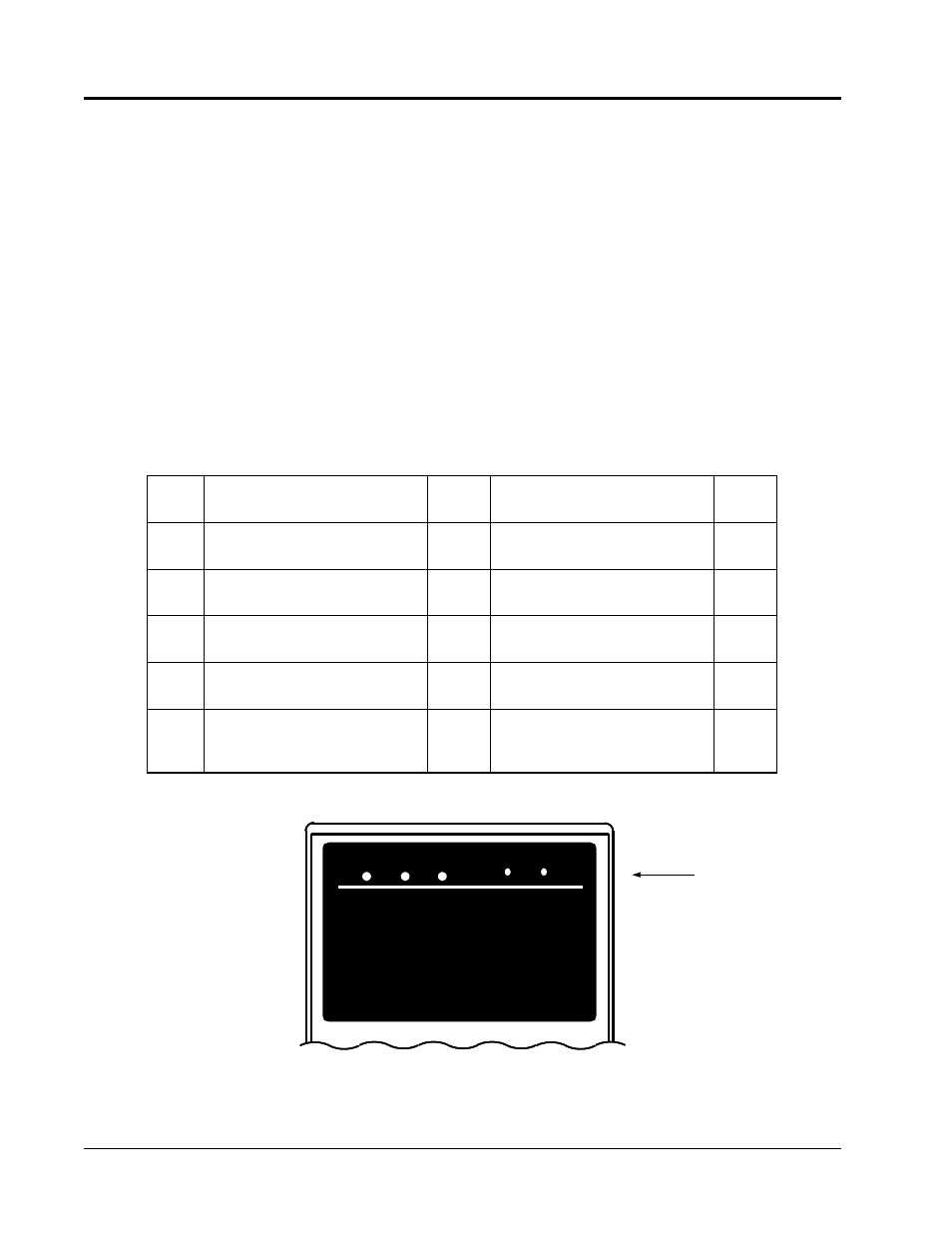
mand only when operation is stopped. The operation mode selected can be verified by observing the SEQ and
REF LEDs on the digital operator (as shown below). The operation mode is set to REMOTE (run by control
circuit terminals 13 and/or 14 frequency reference and run command from control circuit terminals) prior to
shipment. Multi-function contact inputs from control circuit terminals 3 to 8 are enabled in both operation
modes.
· LOCAL:
Both frequency reference and run command are set by the digital operator. SEQ and REF
LEDs go OFF.
· REMOTE: Master frequency reference and run command can be selected as described in the table
below.
Operation Mode Selection
Setting
Reference Selection (B1-01)
REF
LED
Operation Method Selection (B1-02)
SEQ
LED
0
Master frequency reference from digital
operator
OFF
Operation by run command from digital
operator
OFF
1
Master frequency reference from control
circuit terminals 13 and 14
ON
Operation by run command from control
circuit terminal
ON
2
Master frequency reference set by serial
communication
blinking
Operation by run command from serial
communication
blinking
3
Master frequency reference set by
option card
blinking
Operation by run command from option
card
blinking
4
Master frequency reference set by EWS
(Engineering Work Station). This setting
will be used with the CP-717 <1110>.
ON
Operation by run command from EWS
(CP-717) <1110>.
ON
DRIVE FWD
REV
REMOTE
SEQ
REF
ON, OFF or blinking
Figure 18 Operation Mode LEDs
Chapter 2 - Operation
Digital Operator Display