Yaskawa VS-616G5 Series Revision F Quick-Start User Manual
Page 29
VS-616G5 Installation & Quick-Start Manual
29
· Magnetic Starter
Do not connect a magnetic starter or a magnetic contactor to the output circuit. If the motor load is
connected or disconnected while the inverter is running, the inverter overcurrent protective circuitry
may trip.
· Thermal Overload Relay
An Underwriter’s Laboratory (UL) recognized electronic overload protective function is incorpo-
rated into the inverter. However, when driving several motors with one inverter, or when switching
between multiple windings of a multiple winding motor, connect an external thermal overload relay.
In this case, disable the inverter motor overload feature by setting parameter L1-01 to “0”.
· Wiring Distance Between Inverter and Motor
If the total wiring distance between inverter and motor is excessively long and the inverter carrier
frequency (IGBT switching frequency) is high, harmonic leakage current from the wiring may
adversely affect the inverter and peripheral devices. If the wiring distance is long, reduce the inverter
carrier frequency as described below. Carrier frequency can be set by parameter C6-01. Please note
that motor audible noise may increase when lowering the carrier frequency.
Wiring Distance Between Inverter and Motor
Grounding
· Ground Resistance
230V class: 100
Ω or less, 460V class: 10Ω or less, 575V class: 10Ω or less.
· Never ground the VS-616G5 in common with welding machines, motors, or other high-current elec-
trical equipment. Run all ground wiring in a separate conduit.
· Use ground wiring as specified in “Wire and Terminal Screw Sizes” on page 31, and keep the length
as short as possible.
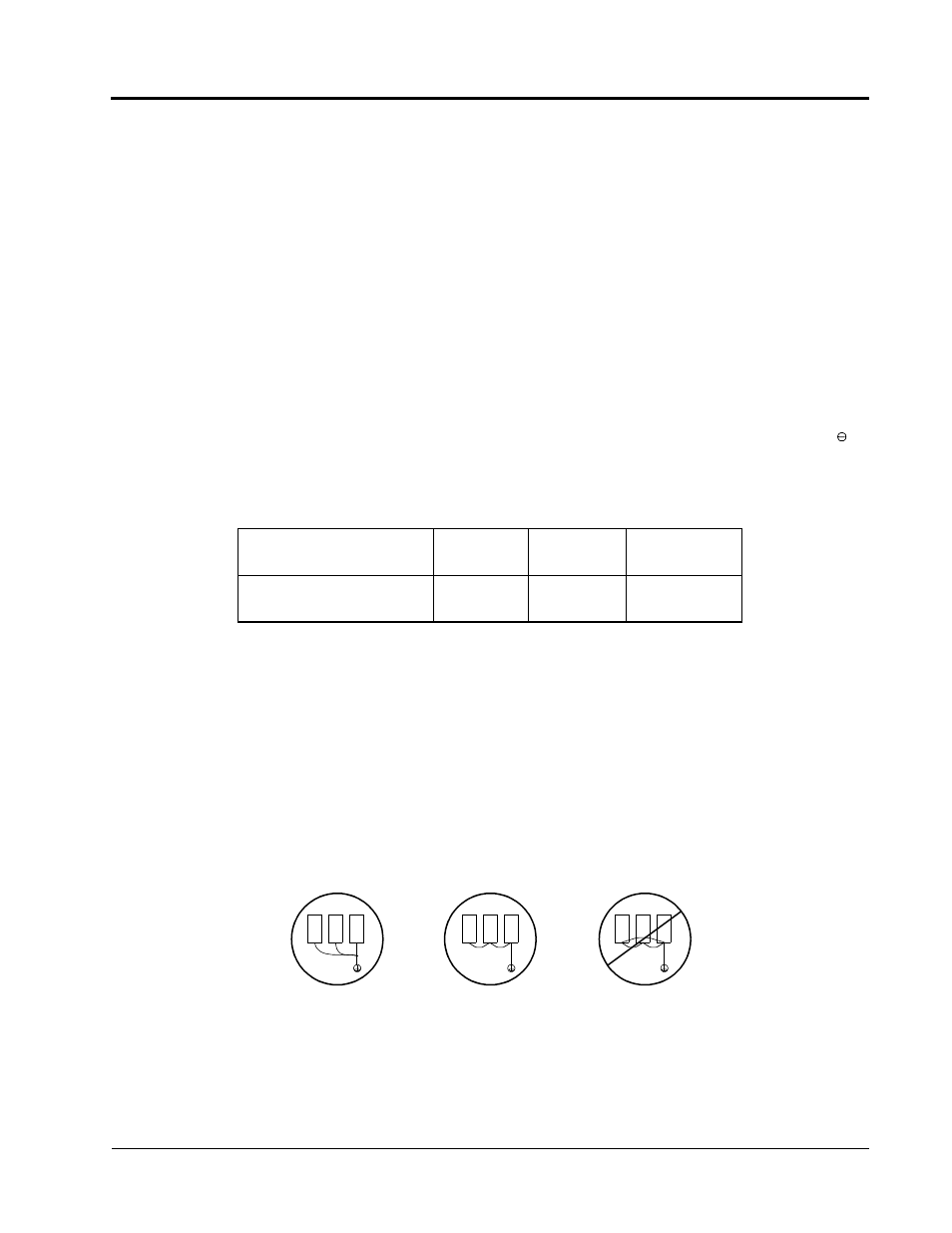
· When using several VS-616G5 units side by side, ground the units as shown in Figure 12, (a) or (b).
Do not loop the wires as shown in (c).
Wiring Distance between
Inverter and Motor
Up to 164 ft.
(50m)
Up to 328 ft.
(100m)
More than 328 ft.
(100m)
Carrier Frequency
(Set value of parameter C6-01)
15kHz or less
10kHz or less
5kHz or less
Figure 12 Grounding Example of 3 VS-616G5 Inverters
(a) Acceptable
(b) Acceptable
(c) Not Acceptable
Chapter 1 - Receiving & Installation
Wiring