Yaskawa VS-616G5 Series Revision F Quick-Start User Manual
Page 99
96
VS-616G5 Installation & Quick-Start Manual
Te
rmi
nal
Fun
cti
on
Func
tion H1
Di
gi
ta
l In
puts
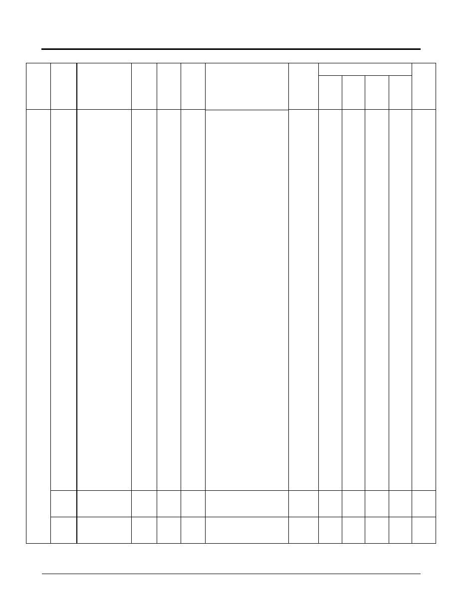
H1-01
Terminal 3
Selection
(Terminal 3 Sel)
00~77
1
24
Multi-function input (terminal 3)
0: 3-Wire Control
1: Local/Remote Selection
2: Option/Inverter Selection
3: Multi-Step Reference 1
4: Multi-Step Reference 2
5: Multi-Step Reference 3
6: Jog Frequency Reference
7: Multi-Accel/Decel 1
8: External Baseblock N.O.
9: External Baseblock N.C.
A: Accel/Decel Ramp Hold
B: OH2 Alarm Signal
C: Terminal 16 Enable
D: V/F Mode Select
E: ASR Integral Reset
F: Terminal Not Used
10: MOP Increase
11: MOP Decrease
12: Forward Jog
13: Reverse Jog
14: Fault Reset
15: Fast-Stop N.O.
16: Motor 2 Select
17: Fast Stop N.C. input
<1110>
18: Timer Function
19: PID Disable
1A: Multi-Accel/Decel 2
1B: Program Lockout
1C: Trim Control Increase
1D: Trim Control Decrease
1E: Ref Sample Hold
1F: Terminal 13/14 Switch
24: External Fault
30: PID Integral Reset
31: PID Control Integral Hold
<1110>
60: DC Injection Activate
61: Speed Search 1
62: Speed Search 2
63: Energy Save Mode
64: Speed Search 3
65: KEB Ridethrough N.C.
66: KEB Ridethrough N.O
71: Speed/Torque Control
Change
72: Zero Servo Command
77: ASR Gain Switch
x
B
B
B
B
H1-02
Terminal 4
Selection
(Terminal 4 Sel)
00~77
1
14
Multi-function input (terminal 4)
(same as H1-01)
x
B
B
B
B
H1-03
Terminal 5
Selection
(Terminal 5 Sel)
00~77
1
3 (0)
(Note
15)
Multi-function input (terminal 5)
(same as H1-01)
x
B
B
B
B
Function
Parameter
No.
Name
(Digital Operator
Display)
Setting
Range
Setting
Unit
Factory
Setting
Remarks
(Digital Operator Display)
Change
during
Operation
o: Enabled
x: Disabled
Parameter Access Level
User
Setting
V/f
V/f
w/
PG
Open
Loop
Vector
Flux
Vector
Appendix
VS-616G5 Parameters