Physical layer interface signals, Serial data signals, Pipe interface signals – Altera Arria 10 Avalon-ST User Manual
Page 123: Physical layer interface signals -57, Serial data signals -57, Pipe interface signals -57
Physical Layer Interface Signals
Altera provides an integrated solution with the Transaction, Data Link and Physical Layers. The IP
Parameter Editor generates a SERDES variation file,
<variation>_serdes.v
or .vhd , in addition to the Hard
IP variation file,
<variation>.v
or
.vhd
. The SERDES entity is included in the library files for PCI Express.
Serial Data Signals
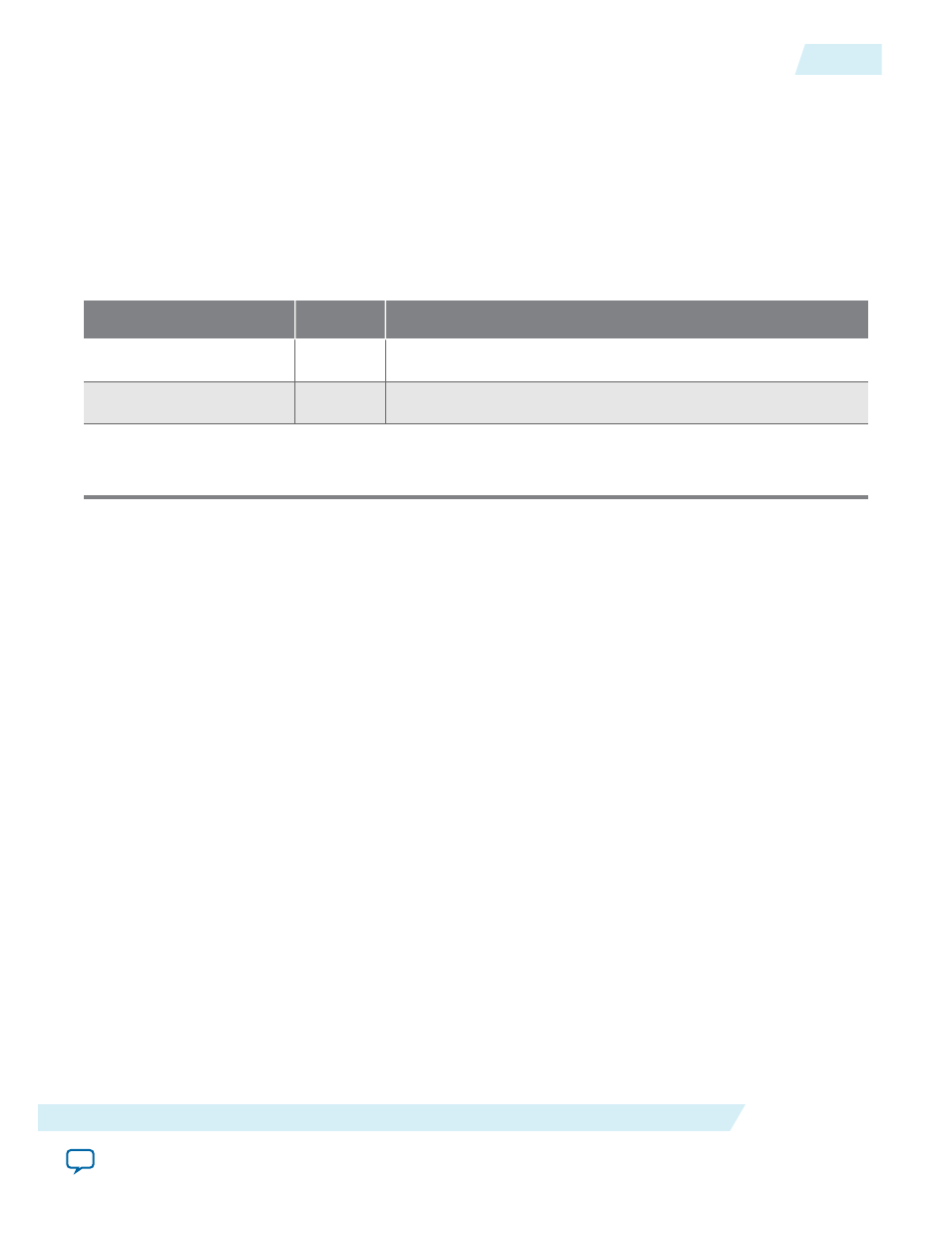
Table 6-21: 1-Bit Interface Signals
Signal
Direction
Description
tx_out[7:0]
(1)
Output
Transmit output. These signals are the serial outputs of lanes 7–0.
rx_in[7:0]
(1)
Input
Receive input. These signals are the serial inputs of lanes 7–0.
Note:
1. The x1 IP core only has lane 0. The x2 IP core only has lanes 1–0. The x4 IP core only has lanes 3–0.
Refer to Pin-out Files for Altera Devices for pin-out tables for all Altera devices in .pdf, .txt, and .xls
formats.
Transceiver channels are arranged in groups of six. For GX devices, the lowest six channels on the left side
of the device are labeled GXB_L0, the next group is GXB_L1, and so on. Channels on the right side of the
device are labeled GXB_R0, GXB_R1, and so on. Be sure to connect the Hard IP for PCI Express on the
left side of the device to appropriate channels on the left side of the device, as specified in the Pin-out Files
for Altera Devices.
Related Information
•
Physical Layout of Hard IP In Arria 10 Devices
•
PIPE Interface Signals
These PIPE signals are available for Gen1, Gen2, and Gen3 variants so that you can simulate using either
the serial or the PIPE interface. Simulation is much faster using the PIPE interface because the PIPE
simulation bypasses the SERDES model . By default, the PIPE interface is 8 bits for Gen1 and Gen2 and 32
bits for Gen3. You can use the PIPE interface for simulation even though your actual design includes a
serial interface to the internal transceivers. However, it is not possible to use the Hard IP PIPE interface in
hardware, including probing these signals using SignalTap
®
II Embedded Logic Analyzer.
Note: The Altera Root Port BFM bypasses Gen3 Phase 2 and Phase 3 Equalization. However, Gen3
variants can perform Phase 2 and Phase 3 equalization if instructed by a third-party BFM.
In the following table, signals that include lane number 0 also exist for lanes 1-7.
UG-01145_avst
2015.05.04
Physical Layer Interface Signals
6-57
Interfaces and Signal Descriptions
Altera Corporation