Altera Arria 10 Avalon-ST User Manual
Page 125
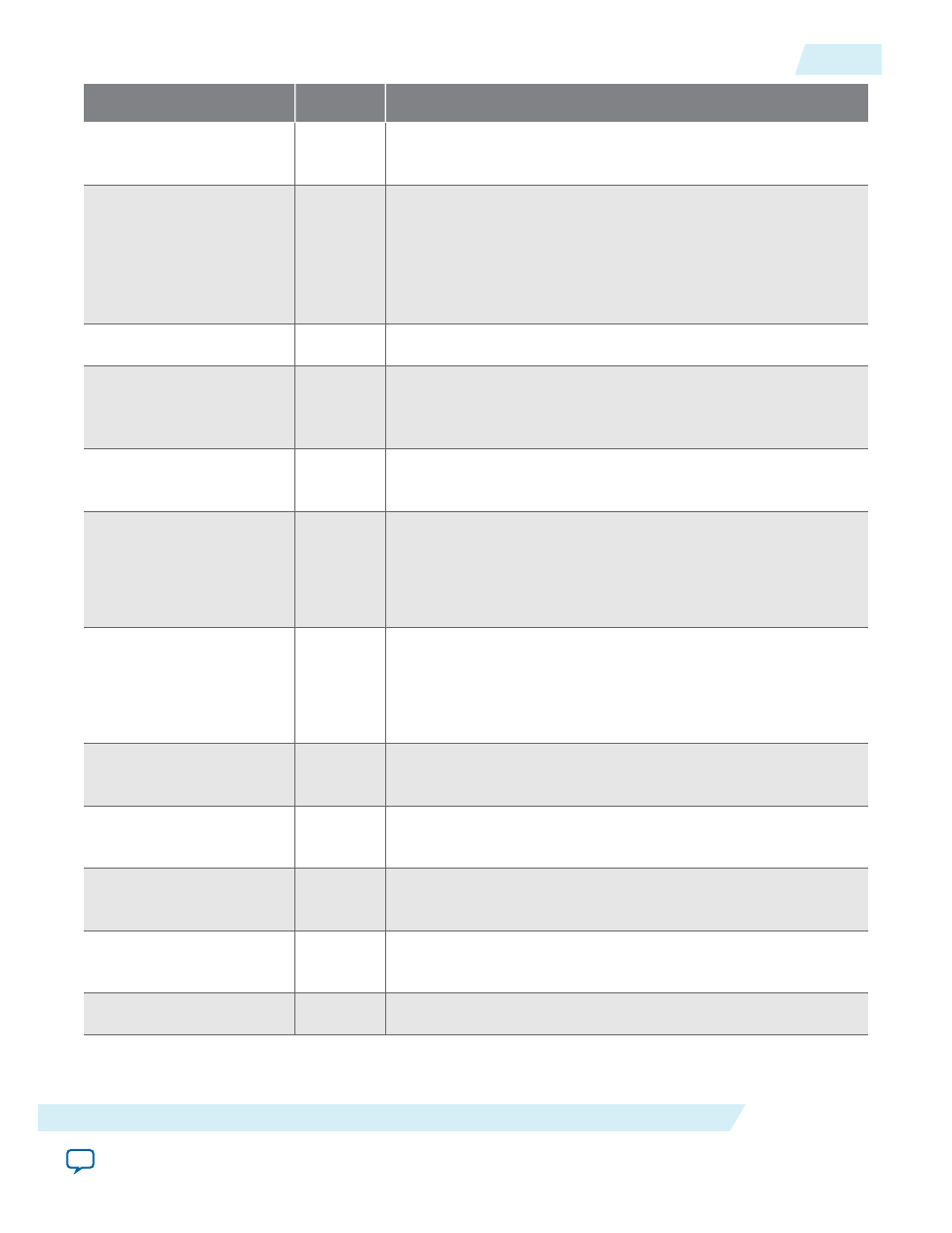
Signal
Direction
Description
powerdown0[1:0]
Output
Power down <n>. This signal requests the PHY to change its
power state to the specified state (P0, P0s, P1, or P2).
currentcoeff0[17:0]
Output
For Gen3, specifies the coefficients to be used by the transmitter.
The 18 bits specify the following coefficients:
• [5:0]: C
-1
• [11:6]: C
0
• [17:12]: C
+1
currentrxpreset0[2:0]
Output
For Gen3 designs, specifies the current preset.
tx_margin[2:0]
Output
Transmit V
OD
margin selection. The value for this signal is based
on the value from the
Link Control 2
Register
. Available for
simulation only.
txswing
Output
When asserted, indicates full swing for the transmitter voltage.
When deasserted indicates half swing.
txsynchd0[1:0]
Output
For Gen3 operation, specifies the transmit block type. The
following encodings are defined:
• 2'b01: Ordered Set Block
• 2'b10: Data Block
rxsynchd0[1:0]
Input
For Gen3 operation, specifies the receive block type. The
following encodings are defined:
• 2'b01: Ordered Set Block
• 2'b10: Data Block
rxvalid0
(1)
Input
Receive valid <n>. This signal indicates symbol lock and valid
data on
rxdata
<n> and
rxdatak
<n>.
phystatus0
(1)
Input
PHY status <n>. This signal communicates completion of several
PHY requests.
rxelecidle0
(1)
Input
Receive electrical idle <n>. When asserted, indicates detection of
an electrical idle.
rxstatus0[2:0]
(1)
Input
Receive status <n>. This signal encodes receive status, including
error codes for the receive data stream and receiver detection.
simu_mode_pipe
Input
When set to 1, the PIPE interface is in simulation mode.
UG-01145_avst
2015.05.04
PIPE Interface Signals
6-59
Interfaces and Signal Descriptions
Altera Corporation