Single packet per cycle – Altera Arria 10 Avalon-ST User Manual
Page 95
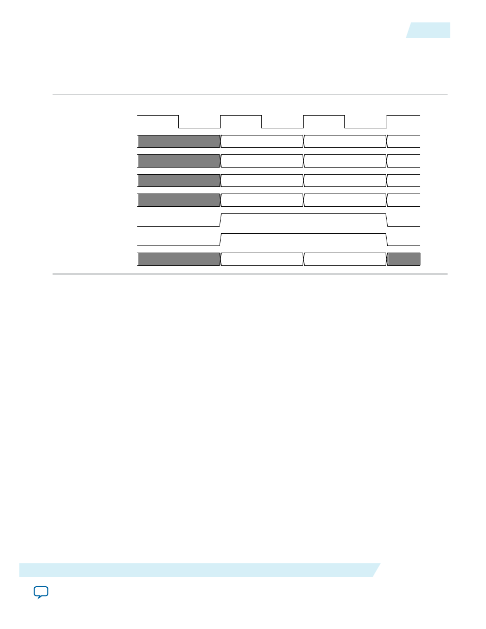
Figure 6-30: 256-Bit Avalon-ST tx_st_data Cycle Definition for 3-Dword Header TLP with Qword
Addresses
The following figure illustrates the layout of header and data for a three dword header on a 256-bit bus
with aligned and unaligned data.
01
10
clk
tx_st_data[63:0]
Aligned Data
Unaligned Data
tx_st_data[127:64]
tx_st_data[191:128]
tx_st_data[255:192]
tx_st_sop
tx_st_eop
tx_st_empty[1:0]
Header 1 Header 0
XXXXXXXX Header 2
XXXXXXXX Data 0
XXXXXXXXX XXXXXXXX
Header 1 Header 0
Data 0 Header 2
XXXXXXXXX XXXXXXXX
XXXXXXXXX XXXXXXXX
Single Packet Per Cycle
In single packer per cycle mode, all received TLPs start at the lower 128-bit boundary on a 256-bit
Avalon-ST interface. Turn on Enable Multiple Packets per Cycle on the System Settings tab of the
parameter editor to change multiple packets per cycle.
Single packet per cycle mode requires simpler Application Layer packet decode logic on the TX and RX
paths because packets always start in the lower 128-bits of the Avalon-ST interface. Although this mode
simplifies the Application Layer logic, failure to use the full 256-bit Avalon-ST may slightly reduce the
throughput of a design.
The following figure illustrates the layout of header and data for a three dword header on a 256-bit bus
with aligned and unaligned data.
UG-01145_avst
2015.05.04
Single Packet Per Cycle
6-29
Interfaces and Signal Descriptions
Altera Corporation