Removing the aib/eaib chassis – Adept s650HS Quattro User Manual
Page 162
Chapter 9: Maintenance - HS
CAUTION: Follow appropriate ESD procedures during
the removal/replacement steps.
Removing the AIB/eAIB Chassis
1. Switch OFF the SmartController.
2. Switch OFF the 24 VDC input supply to the AIB/eAIB chassis.
3. Switch OFF the 200-240 VAC input supply to the AIB/eAIB chassis.
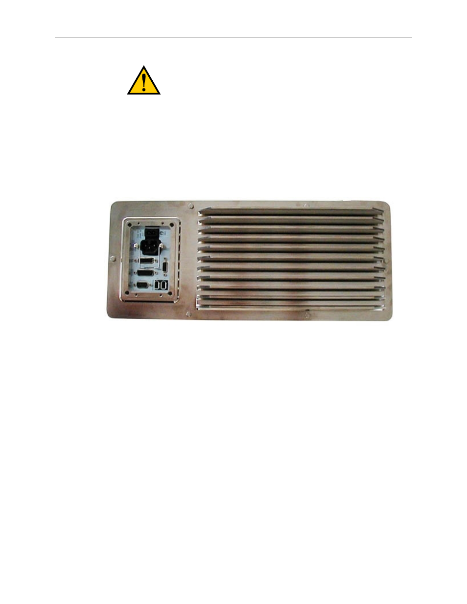
4. Unscrew the six M4 chassis securing bolts. See the following figure.
Figure 9-1. Securing Bolts on Chassis, AIB Shown
l
These bolts were installed using Loctite 222.
l
Retain the bolts for reinstallation.
NOTE: The AIB/eAIB on the Quattro HS robots can be difficult to remove after the
cable inlet box has been removed. You should lift the AIB/eAIB slightly, to loosen
the seal, before proceeding.
5. Remove the cable inlet box. See Removing and Installing the Cable Inlet Box on page
6. Disconnect the 24 VDC supply cable from the chassis +24 VDC input connector. See
Figure 4-2 for locations of connectors.
7. Disconnect the 200-240 VAC supply cable from the chassis AC input connector.
Lock out and tag out AC power.
8. Disconnect the XSYS cable from the chassis XSLV connector (AIB) or XSYS cable and
eAIB XSLV Adapter cable (eAIB) from the chassis XSYSTEM connector
Adept Quattro User's Guide, Rev F
Page 162 of 196