Adept s650HS Quattro User Manual
Page 30
Chapter 2: Robot Installation - H
degradation in robot performance due to frame motions. Applications requiring higher than 6
kg * 10 g forces across the belt and/or 6 kg * 3 g along the belt may require a stiffer frame
design.
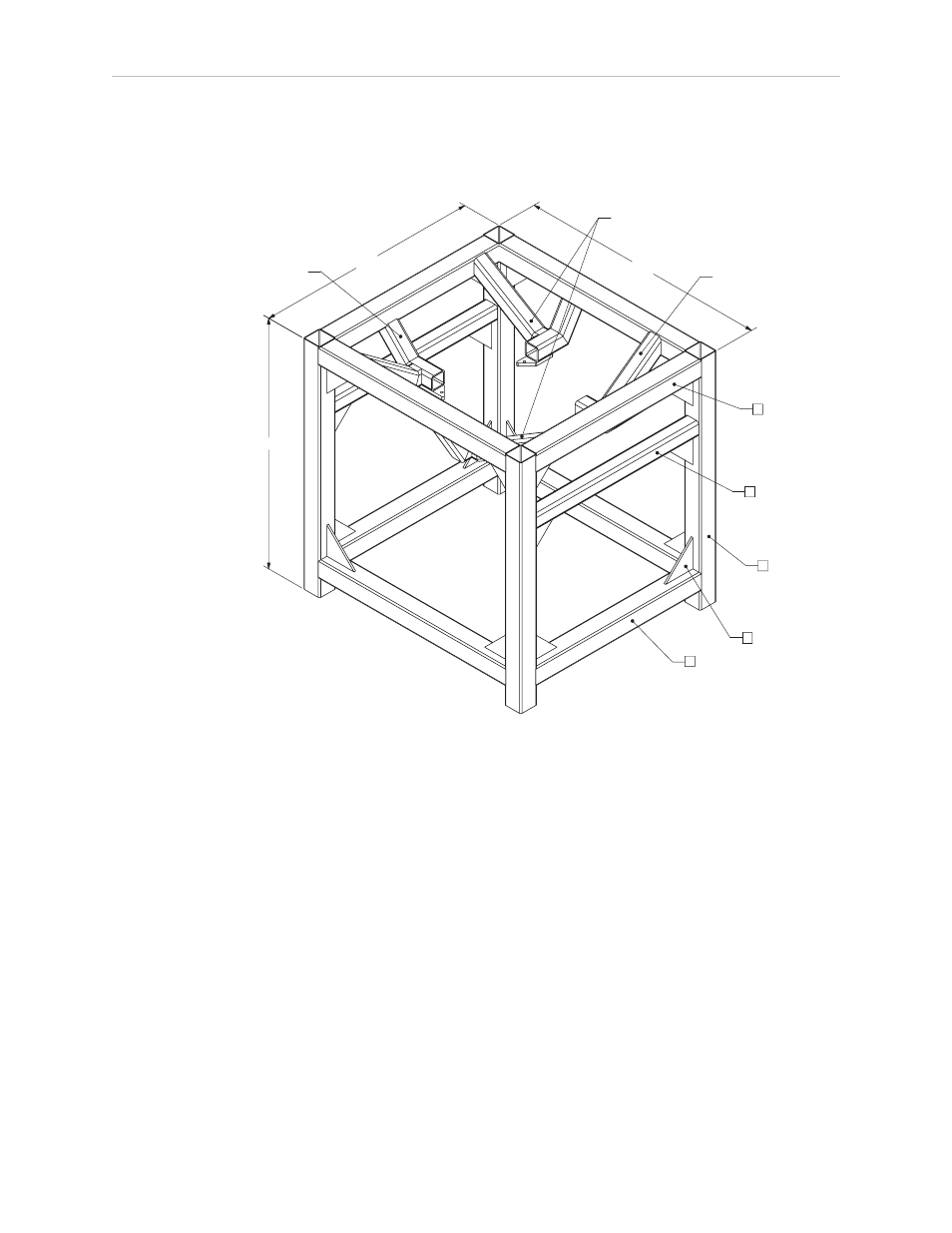
* DIMENSIONS ARE IN MILLIMETERS
UNLESS OTHERWISE SPECIFIED:
MATERIAL : 300 SERIES STAINLESS STEEL
MATERIAL SIZING:
150mm X 150mm X 6mm SQUARE STRUCTURAL TUBING
A.
120mm X 120mm X 10mm SQUARE STRUCTURAL TUBING
B.
250mm X 250mm X 15mm TRIANGULAR GUSSET
C.
A
4x
A
4x
2x
B
SEE DETAIL 1
20x
A
4x
C
SEE DETAIL 2
SEE DETAIL 1
1800.0
2000.0
2000.0
Figure 2-3. Sample Quattro Mounting Frame
Any robot’s ability to settle to a fixed point in space is governed by the forces, masses, and
accelerations of the robot. Since “every action has an equal and opposite reaction”, these forces
are transmitted to the robot frame and cause the frame and base of the robot to move and
possibly vibrate in space. As the robot system works to position the tool flange relative to the
base of the robot, any frame or base motion will be “unobservable” to the robot system, and
will be transmitted to the tool flange. This transmitted base motion will result in inertial
movement of the tool flange mass, and will cause disturbance forces to be introduced into the
robot control system. These disturbance forces cause “work” to be done by the robot servo
control system which may result in longer settling times for robot operations.
Adept Quattro User's Guide, Rev F
Page 30 of 196