Details for 24 vdc mating connector, Procedure for creating 24 vdc cable – Adept s650HS Quattro User Manual
Page 77
Chapter 4: System Installation
Table 4-3. Recommended 24 VDC Power Supplies
Vendor Name
Model
Ratings
XP Power
JPM160PS24
24 VDC, 6.7 A, 160 W
Mean Well
SP-150-24
24 VDC, 6.3 A, 150 W
Astrodyne
ASM150-24
24 VDC, 6.66 A, 150 W
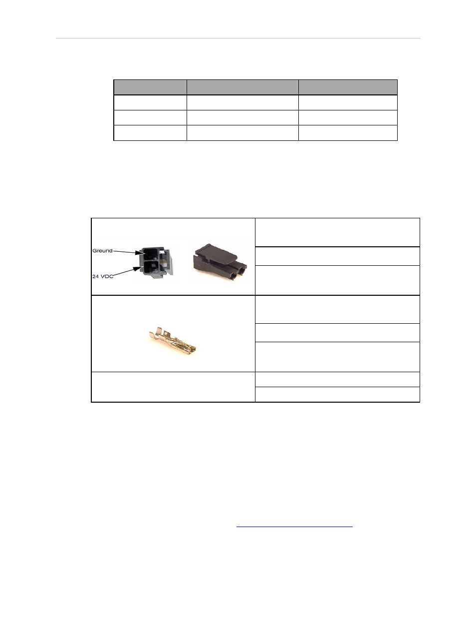
Details for 24 VDC Mating Connector
The 24 VDC mating connector and two pins are supplied with each system. They are shipped
in the cable/accessories box.
Table 4-4. 24 VDC Mating Connector Specs
Connector Details
Connector receptacle, 2 position, type:
Molex Saber, 18 A, 2-Pin
Molex P/N 44441-2002
Digi-Key P/N WM18463-ND
Pin Details
Molex connector crimp terminal,
female, 14-18 AWG
Molex P/N 43375-0001
Digi-Key P/N WM18493-ND
Recommended crimping tools:
Molex P/N 63811-0400
Digi-Key P/N WM9907-ND
Procedure for Creating 24 VDC Cable
NOTE: The 24 VDC cable is not supplied with the system, but is available in the
optional Power Cable kit. See Table 4-1.
1. Locate the connector and pins shown in the preceding table.
2. Use 14-16 AWG wire to create the 24 VDC cable. Select the wire length to safely reach
from the user-supplied 24 VDC power supply to the robot base.
NOTE: A separate 24 VDC cable is required for the SmartController. That cable uses
a different style of connector. See the
Adept SmartController User’s Guide
.
Adept Quattro User's Guide, Rev F
Page 77 of 196