Step 2, Step 3, Auto-zone basic – Auto-Zone Control Systems Auto-Zone Basic Systems Installation & Operation (Version 02C) User Manual
Page 136
Section 4
Auto-Zone Basic
4-34
Start-Up and Troubleshooting
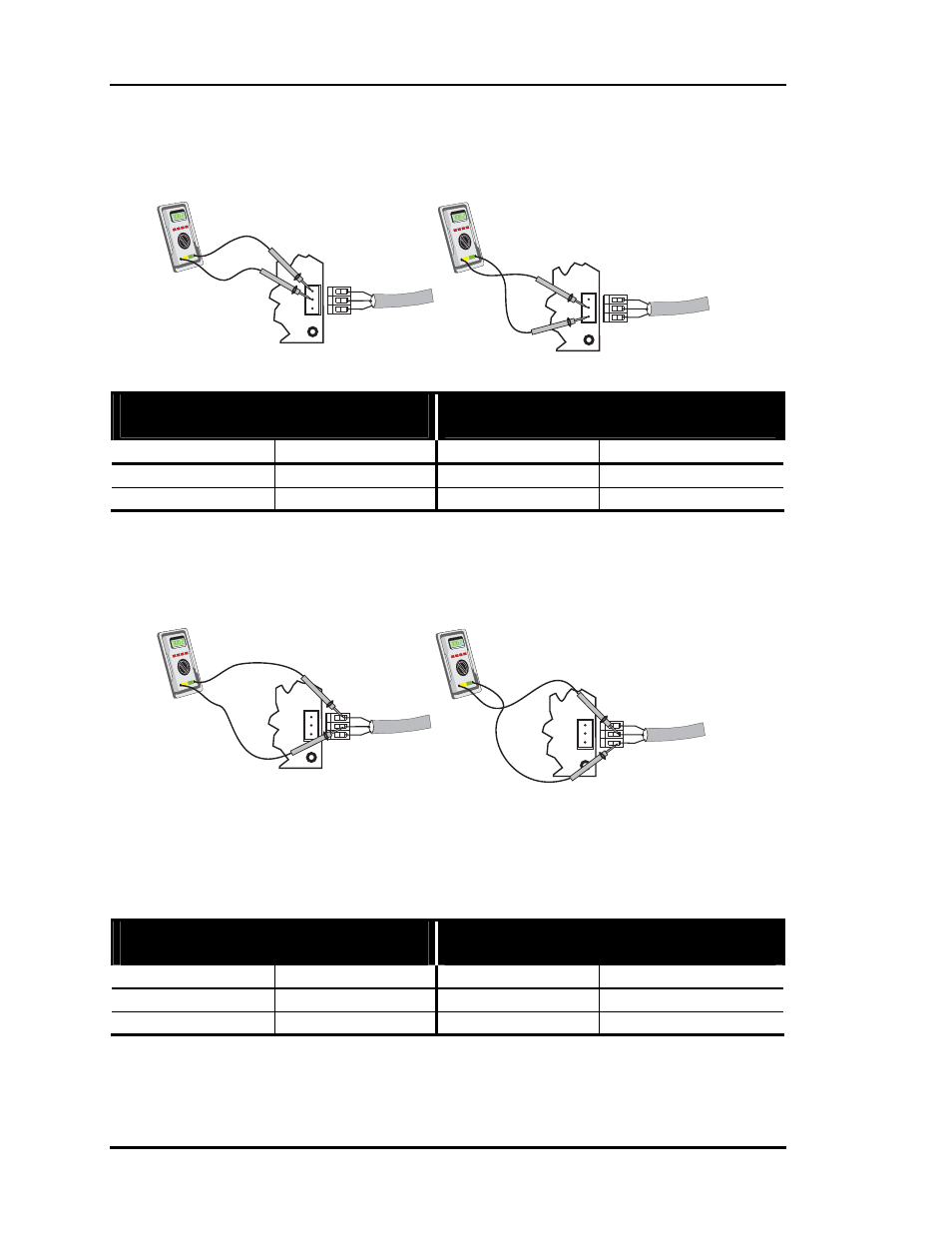
Step 2
Measure the voltage at the Zone Manager terminals with the Communications Loop dis-
connected from the Zone Manager.
Step 3
Measure the voltage on the Communications Loop terminals with the Communications
Loop disconnected from the Zone Manager.
Basic System - Without Optional
CommLink Installed
Basic System - With Optional
CommLink Installed
Measure Voltage Measure Voltage
T to SHLD
+ 2.5 to 2.3 VDC
T to SHLD
+ 2.5 to 2.3 VDC
R to SHLD
+ 2.8 to 2.6 VDC
R to SHLD
+ 2.8 to 2.6 VDC
If the voltages are not within the specified voltage ranges, the Zone Manager communi-
cation driver chip is probably damaged and will require replacement. If the measured
voltages are within the specified voltage range, the Zone Manager driver chip is not dam-
aged, and the problem is related to another part of the loop. Proceed to Step 3.
Basic System - Without Optional
CommLink Installed
Basic System - With Optional
CommLink Installed
Measure Voltage Measure Voltage
T to SHLD
+ 2.5 to 2.4 VDC
T to SHLD
+ 3.2 to 2.7 VDC
R to SHLD
+ 2.5 to 2.4 VDC
R to SHLD
+ 2.3 to 1.9 VDC
If the voltages are not within the specified range when checking the communications
loop as described above, then one of the Zone Controllers or the optional CommLink (if
installed) is the problem. Proceed to the Zone Controller Troubleshooting Section. If a
CommLink is installed, also see the CommLink Troubleshooting Section.
T
R
COMM
TB8
SHLD
+
-
+
-
T
R
COMM
TB8
SHLD
+
-
+
-
Measuring R to SHLD
Measuring T to SHLD
T
R
COMM
TB8
SHLD
+
-
+
-
T
R
COMM
TB8
SHLD
+
-
+
-
Measuring R to SHLD
Measuring T to SHLD