Setpoint screen #5a, Setpoint screen #5b, Setpoint screen #6 – Auto-Zone Control Systems Auto-Zone Basic Systems Installation & Operation (Version 02C) User Manual
Page 80: Auto-zone basic
Section 3
Auto-Zone Basic
3-12 Programming
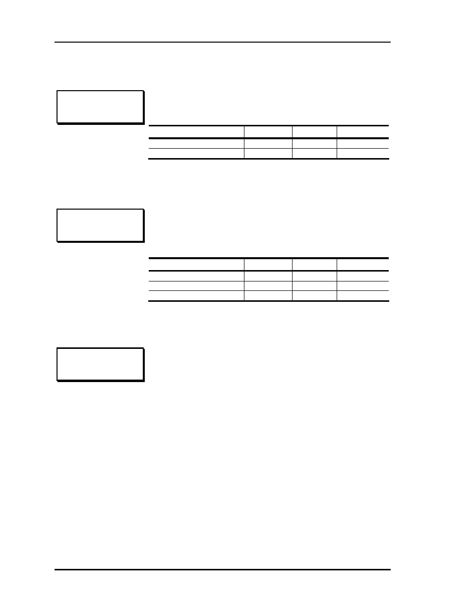
Setpoint Screen #5A
Minimum
Default Maximum
PD Zone Vent Mode Min
0%
50%
100%
PD Zone Nite Mode Min
0%
100%
100%
Setpoint Screen #5B
Minimum
Default Maximum
PI Zone Vent Mode Min
0 CFM
500 CFM
30000 CFM
PI Zone Nite Mode Min
0 CFM
0 CFM
30000 CFM
PI Zone CFM @1" WG
0 CFM
2100 CFM
30000 CFM
Setpoint Screen #6
On Pressure Dependent Zones, the setpoints displayed are for
damper position.
PD ZONE ADDRESS 1
Vent Mode Min.: 50%
Nite Mode Min.: 100%
For Pressure Independent Zones the text changes to display
airflow (CFM) values. On the third line - "CFM@1" WG",
enter the appropriate "K" Flow Factor from Table 1-2 of this
manual.
PD ZONE ADDRESS 1
Vent Mode xxxxx CFM
Nite Mode xxxxx CFM
CFM @1”WG xxxxx CFM
PD ZONE ADDRESS 1
Overrides..: Global
Damper Mode: Direct
PRESS (*) TO TOGGLE
The Zone Controller will respond to another zone’s push-
button override if it is configured for global overrides. If single
overrides are selected, the zone will only enter override if its
own push-button is pressed.
The normal damper operation is direct acting, which means it
opens in a clockwise direction. If your system opens in a
counter-clockwise direction, select reverse acting mode.