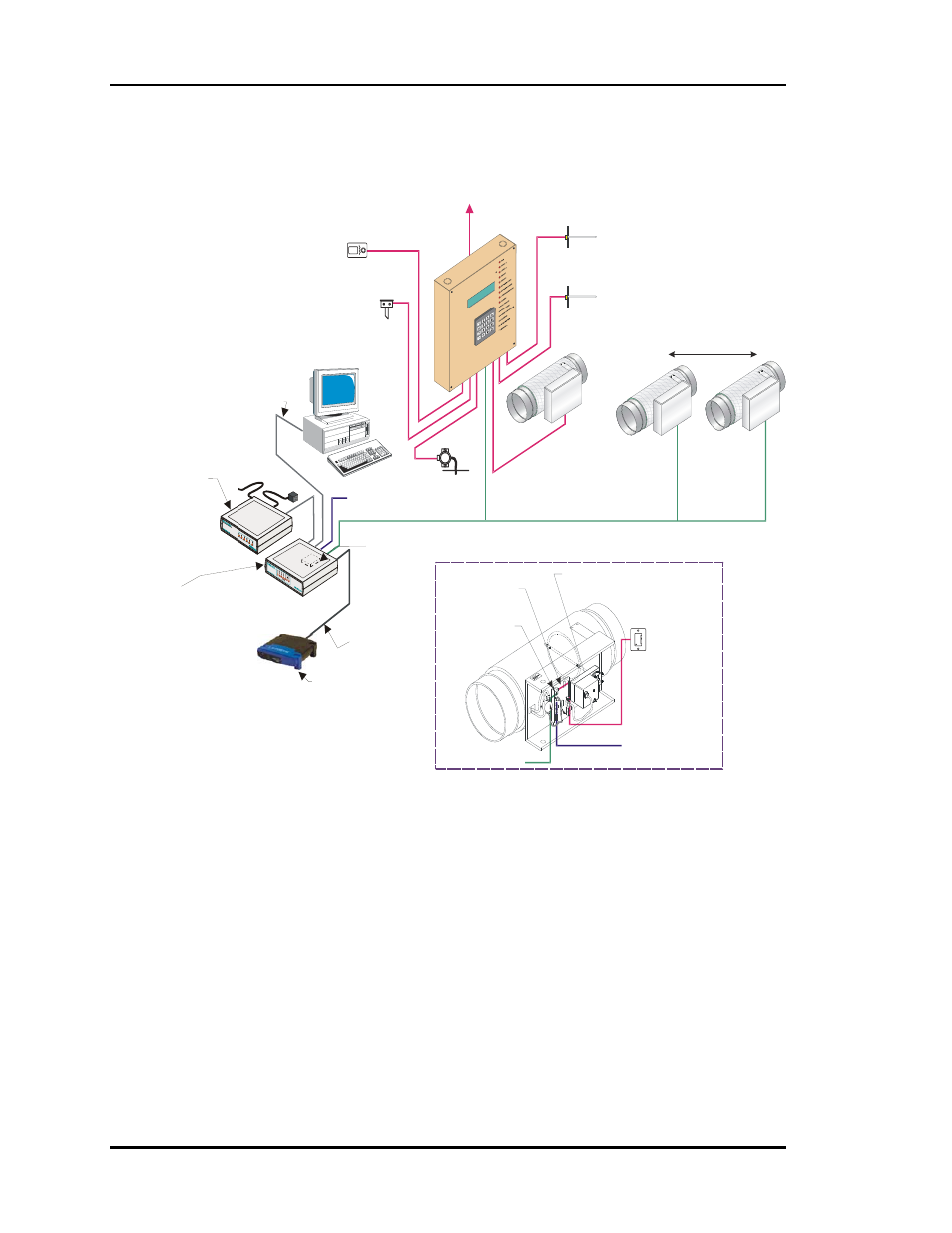
Auto-zone basic, 2 design guide, Figure 1-1: auto-zone basic control system – Auto-Zone Control Systems Auto-Zone Basic Systems Installation & Operation (Version 02C) User Manual
Page 8
Section 1
Auto-Zone Basic
1-2 Design
Guide
Computer
(Optional)
Zone Air Dampers
Up to 16 Zone Air Dampers Allowed
Supply
Air Temp
Sensor
To HVAC Unit
Control Panel
Return
Air Temp
Sensor
Bypass Air
Damper
Economizer
(Actuator By Others)
Outside
Air Temp
Sensor
Static
Pressure
Sensor
#1
#16
Typical Zone
Velocity Sensor
(Optional)
Zone Controller
Damper Actuator
RS-485
Comm Loop
24 VAC
Room Sensor
with Optional
Override & Adj.
Single Loop
RS-485
9600 Baud
24VAC
Remote Link II
(Optional)
Optional IP Module
Installs Into CommLink IV
And Provides
LAN And Internet
Communications
With The Control System
Ethernet Router
(By Others)
When IP Module
Option Is Used
Optional Remote Link II
Connects to CommLink IV
And Provides Alarm Call-Outs
A Second Remote Link Is Required
If Connection To Job Site
Is Desired From Remote Computer
Phone Cable To
Telephone
Wall Outlet Jack
Ethernet Cable To Router
USB Cable To Computer
CommLink IV
The CommLink IV Is
Required For All Systems.
The IP Module, Remote
Link II, And Computer Are
Optional On All Systems.
All Computers Require
Installation of Prism
Graphical User Interface
Software
CommLink IV
Figure 1-1: Auto-Zone Basic Control System