Zone manager, Warning, Auto-zone basic – Auto-Zone Control Systems Auto-Zone Basic Systems Installation & Operation (Version 02C) User Manual
Page 33
Auto-Zone Basic
Section 2
Installation and Wiring
2-3
Zone Manager
The Zone Manager may be installed in any convenient, protected location. Observe the
recommended environmental limitations for the Zone Manager (see Technical Data sec-
tion of product data sheet) when choosing a location. The unit should be mounted with
the display at eye level for easy viewing.
When installing the Zone Manager with display and keypad, you must remove the cover.
Use care not to damage the display while handling and protect the display from physical
damage while removed.
The ribbon cable should be unplugged from the display board which is mounted inside
the front cover. The ribbon cable is keyed to prevent a reverse connection.
Warning:
Always remove power before connecting or disconnecting the ribbon
cable which joins the display and keypad to the Zone Manager. Fail-
ure to observe this precaution may result in damage to the display or
Zone Manager.
The Zone Manager may be mounted without removing the controller from the enclosure
or mounting plate. The unit is mounted by four (4) screws in the corners. Select the cor-
rect screws or other fasteners for the type of mounting material being utilized.
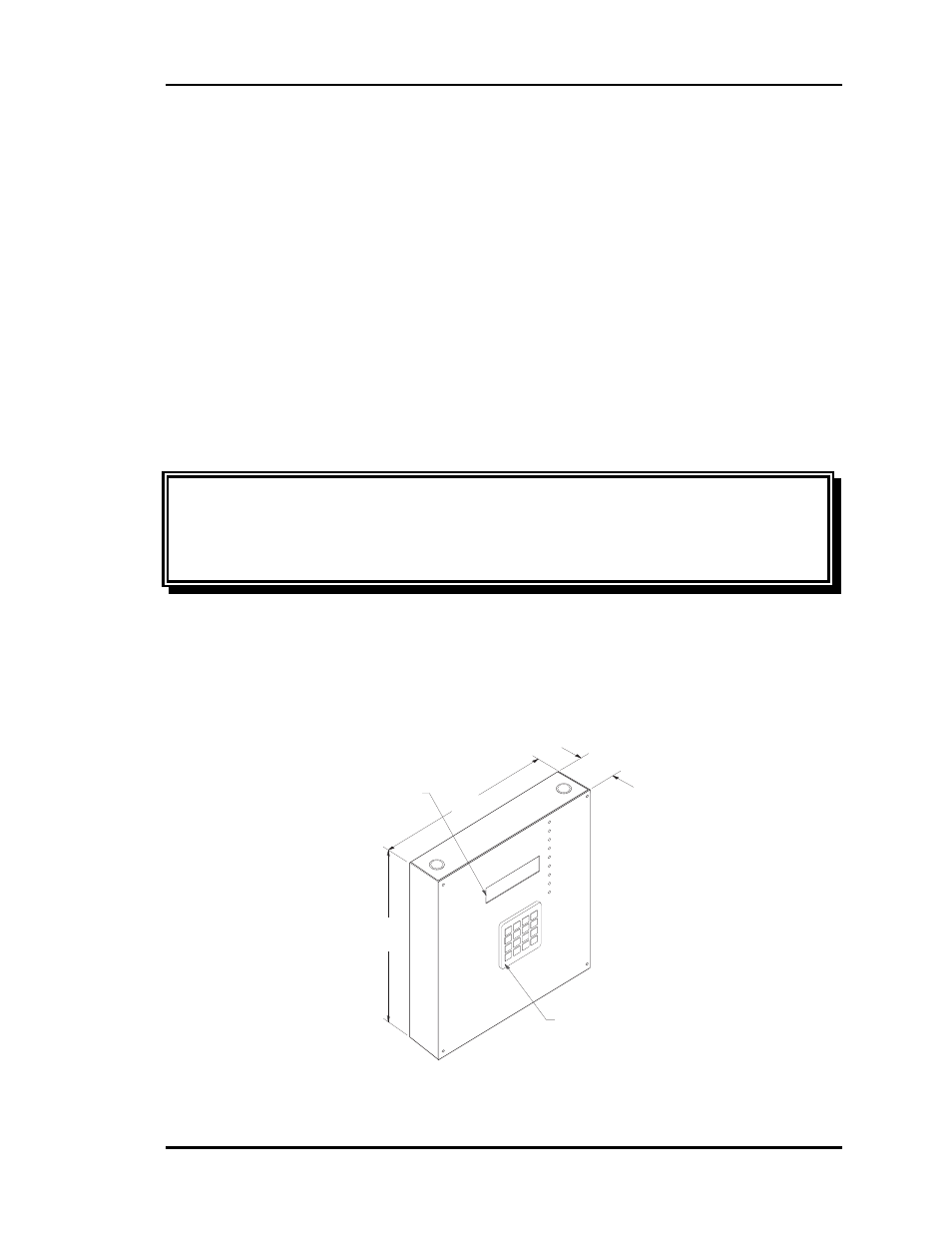
Please see Figure 2-3, Figure 2-4, Figure 2-5, and Figure 2-6 for Zone Manager dimen-
sions, components, wiring, and addressing information.
Figure 2-3: Zone Manager Dimensions
FA
N
CO
OL
1
CO
OL
2
HEA
T 1
HEA
T 2
BYP
AS
S O
PEN
BYP
ASS
CLO
SE
CO
MM
UN
ICA
TIO
N
ALA
RM
A =
ALL
ZO
NE
S
B =
EA
CH
ZO
NE
C =
HV
AC
UNIT/CLE
AR
D =
ALA
RM
S
# =
STEP
/EN
TER
*
= D
EC
IM
AL
+
+
+
+
Cool
Mode
08-08-01
03:48PM
FRI
OCCUPIED
NO
ALARMS
2
8
5
0
A
C
B
D
1
7
4
*
3
9
6
#
3.00
11.50
Keypad
Display
9.25