Auto-zone basic, Installation and wiring – Auto-Zone Control Systems Auto-Zone Basic Systems Installation & Operation (Version 02C) User Manual
Page 32
Section 2
Auto-Zone Basic
2-2
Installation and Wiring
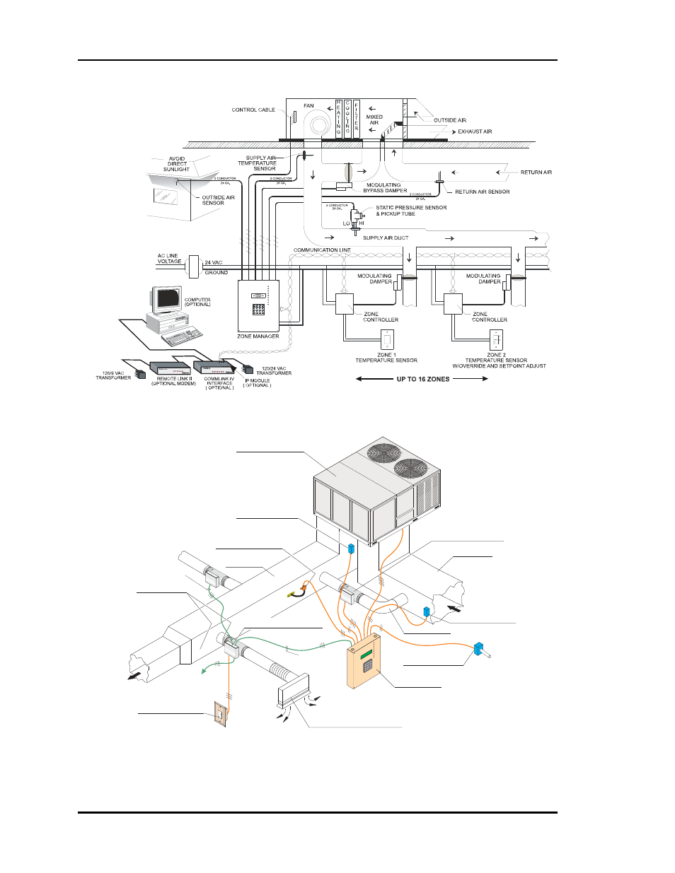
Figure 2-1: System Overview
Figure 2-2: Typical System Component Locations
Return Duct
Duct to Return
Supply Temp Sensor
Return Temp Sensor
(Ahead of Bypass Takeoff)
( Over Corridor for Easy Service )
(2/3 Of The Way Down Main Duct)
(Direct Airflow Inward Towards Center of Area)
(Avoid Mixed Air Area)
(Mount Away From Direct Sunlight))
(Preferred)
Bypass Damper
( Locate Where Easily Accessible )
Static Pressure Pickup
Supply Duct
Zone Damper and Control
Above Corridor
Diffuser at Perimeter Wall
( Preferred Location )
Zone Sensor
Zone Manager
(4-1/2' to 5'; Shoulder Height)
Outdoor Air Sensor
LOCAL COMM LOOP
TWISTED PAIR
WITH SHIELD TO
ZONE CONTROLLER
LOCAL COMM LOOP
TWISTED PAIR
WITH SHIELD TO
ZONE CONTROLLER
LOCAL COMM LOOP
TWISTED PAIR WITH
SHIELD TO OTHER
ZONE CONTROLLERS
NOR
MAL
OVR
W
A
R
M
E
R
C
O
O
L
E
R
FA
N
CO
OL
1
CO
OL
2
HE
AT
1
HE
AT
2
BY
PA
SS
OP
EN
BY
PA
SS
CL
OS
E
CO
MM
UN
ICA
TIO
N
AL
AR
M
A =
AL
L Z
ON
ES
B =
EA
CH
ZO
NE
C =
HV
AC
UN
IT/C
LE
AR
D =
AL
AR
MS
# =
ST
EP
/EN
TE
R
* =
DE
CIM
AL
+
+
+
+
®
2
8
5
0
A
C
B
D
1
7
4
*
3
9
6
#
(Packaged or Split System)
Typical HVAC Unit