Auto-zone basic, Warning – Auto-Zone Control Systems Auto-Zone Basic Systems Installation & Operation (Version 02C) User Manual
Page 144
Section 4
Auto-Zone Basic
4-42
Start-Up and Troubleshooting
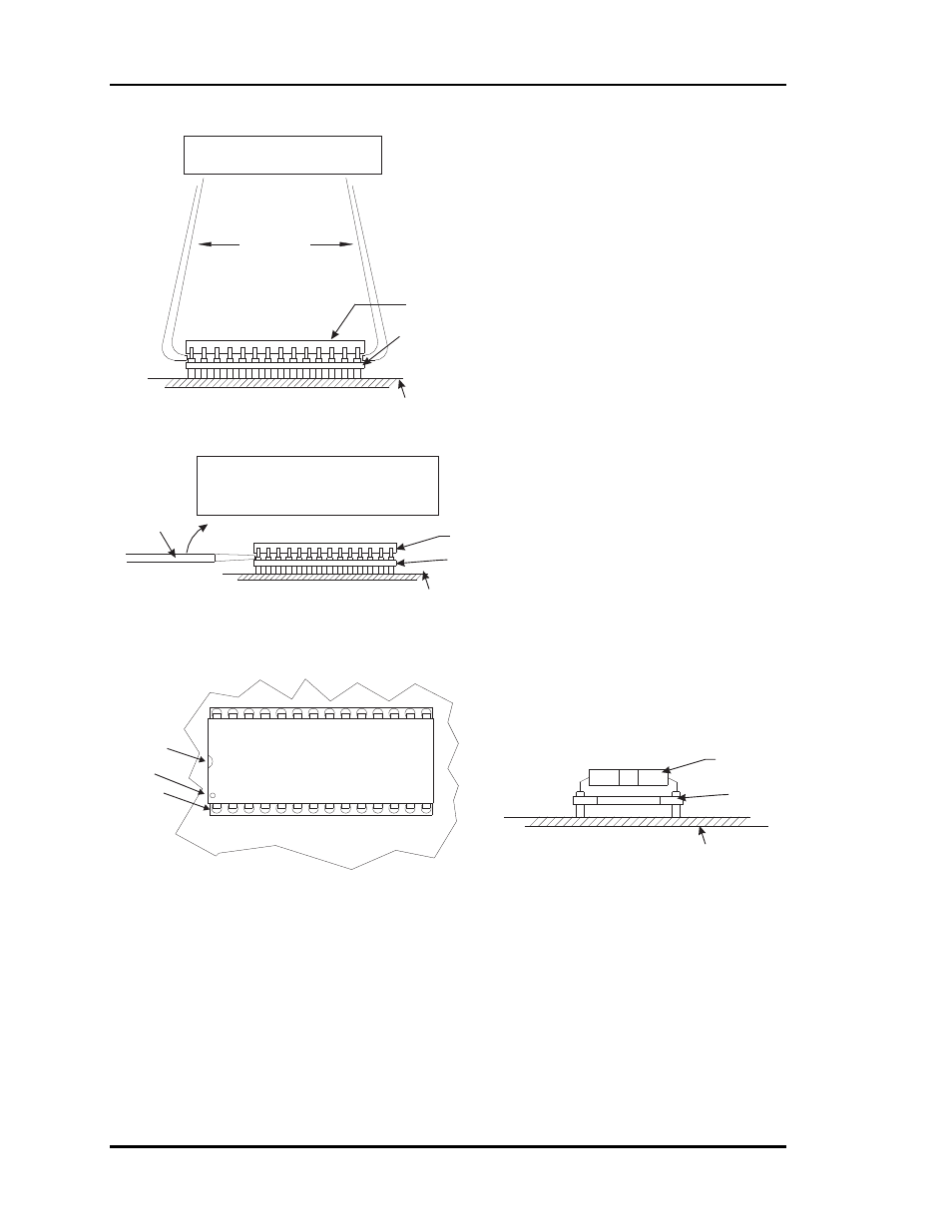
Figure 4-13: Replacing Driver Chips
Small Flathead
Screwdriver
Chip
Chip
Printed Circuit
Board
Printed Circuit
Board
Printed Circuit
Board
Chip
WARNING!
Direction Of Pull
Notch
Dot
Pin1
Be sure the chip you have selected to replace is a
socketed chip. Not all driver chips on the boards
are field replaceable. Only socketed chips may be
removed and replaced in the field. All other chips
that are not socketed will require sending the board
to the WattMaster factory for repair.
Once you have determined that the
chip needing replacement is indeed a socketed chip
please proceed in the following manner.
Remove the communications loop connector and
then the 24VAC power connector on the controller
before attempting to change any components.
will occur if components are removed or
installed with power applied.
If you are unsure how to safely remove the chip or
about the correct pin placement, please consult the
factory before proceeding.
Use extreme care to avoid inserting the screwdriver
or I.C. Puller under the socket. You must insert the tip
of the screwdriver or ends of the I.C. Puller between
the body of the chip and the chip socket.
Each chip
be installed with Pin 1 in the correct
location. Installing the chip “backwards” will in most
cases destroy the device when power is reapplied.
Pin 1 can be located by looking for the notch in the end
of the chip. Pin 1 on "some" chips is identified with a dot.
Be certain that
pins are lined up in the socket
before pressing the chip in. Failure to properly line
up the pins will result in damage to the chip.
This is a
common error -
Only after confirming that the chip has been correctly
installed with Pin 1 in the proper position and that the
pins are lined up and none are bent or out of the socket,
should communication or power wiring be reconnected
to the board. Tp prevent possible damage always
reconnect the power wiring first and then the
communication wiring.
If you try to
remove a chip that is not socketed it will destroy
the circuit board.
DAMAGE
Damage to the board caused by failure to correctly
remove or install the chip is not covered by the
WattMaster warranty.
MUST
ALL
VERY
BE CAREFUL.
Using I.C. Puller To Remove Socketed Chip
Using Screwdriver To Remove Socketed Chip
End View Of Socketed Chip Assembly
Top View Of Socketed Chip Assembly
I.C. Puller
Chip Socket
Chip Socket
Chip Socket
Gently Rock Chip Side To Side And Then
Lift Straight Up To Remove Chip From
Chip Socket.
Gently Lift The Chip On One End And Rock Chip
Back And Forth With Screwdriver As Shown.
Repeat This Process On The Other End Of Chip.
Alternate This Process On Both Ends Of Chip Until
The Chip Is Free From The Chip Socket.