Overview, Parts and descriptions, 11 vcc-x controller technical guide – Orion System VCC-X Controller User Manual
Page 11
OVERVIEW
11
VCC-X Controller Technical Guide
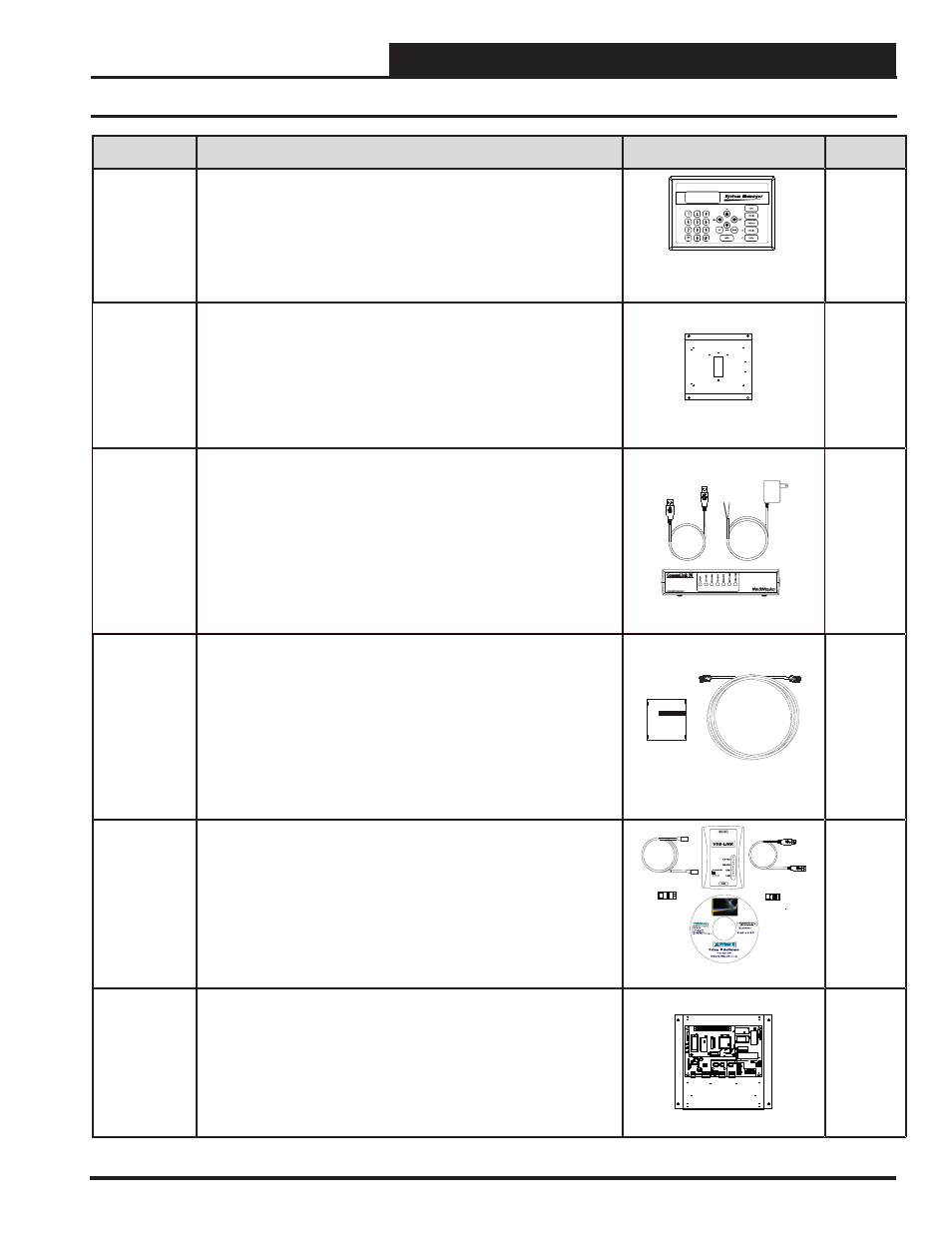
PART NO.
PART DESCRIPTION
ILLUSTRATION
PAGE NO.
OE392-12
Modular System Manager SD
Includes: Modular System Manager SD with 4 Gigabyte SD card and 12 ft.
long pigtail cable assembly. Used to program and monitor all Orion
controllers. Designed for hollow core wall mounting. When System
Manager is to be mounted on a solid wall (concrete), you will also need
to order the solid wall mounting bracket below. Modular System Manager,
power supply, communication cables,
See VCC-X
Controller
Operator
Interfaces
SD
Technical
Guide
EB101505
Solid Wall Mounting Bracket for Modular System Manager
SD
Includes: 22 gauge galvanized sheet metal mounting bracket with mount-
ing holes and wire routing opening. Dimensions are 9.25″W x 8.00″H x
0.50″DP. The Wall Mounting Bracket provides wiring clearance between
the System Manager and the wall mounting surface when the System
Manager is to be mounted on a concrete or other solid wall surface. Not
for use with System Manager TS.
OE361-13
CommLink 5 Communications Interface
The CommLink 5 connects to your control system using a USB computer
connection to provide direct on-site communications with the control
system from a computer with the Prism 2 software installed. For remote
communications, see OE415-02 IP Module Kit.
Includes: CommLink 5, 6 ft. long USB cable, and 120/24 VAC power sup-
ply. Required on all networked systems or if direct computer or remote
computer connection is required. Connects to your computer’s USB 1.1
or 2.1 port. Prism 2 computer front-end software must be installed on the
direct connected or remote connected computer in order to communicate
with your system.
STATUS
See
CommLink
5 Technical
Guide
OE415-02
IP Module Kit - Internet/LAN Connection
Used for Internet or Local Area Network communications with the control
system. Field installs by plugging into the CommLink 5 circuit board and
provides an addressable Ethernet connection to the controls system from
any computer connected to your building’s LAN. It can also be confi gured
to allow access to the control system from the Internet through your LAN if
your Ethernet fi rewall is confi gured for this option.
Includes: IP Link module, 10 ft. long Ethernet cable, and installation
instructions. Prism 2 computer front-end software must be installed on the
remote computer in order to dial-up and communicate with the controls
system.
See IP
Module
Technical
Guide
OE366
USB-Link 2 Kit
The USB-Link 2 is a pocket-sized communications interface used to
connect a laptop computer to your controls system for programming and
monitoring purposes, utilizing a modular cable to allow connection to the
service port connector on the controllers and a USB cable to connect to a
laptop computer.
Includes: USB-Link 2 for multiple or single loop systems, USB cable,
modular connection cable, two mini-DIN to terminal adapters, and Prism 2
software.
See USB-
Link 2
Technical
Guide
OE364-22
MiniLink Polling Device
Control enclosure is for indoor use only. Used with all Orion controllers
to provide network communications, zone voting, alarming, and tenant
logging capabilities. A MiniLink Polling Device is required on each loop
of a Networked system. Includes: MiniLink Polling Device mounted in
the EE000075-01 control enclosure. Control Enclosure cover is shown
removed in picture.
EPROM
U3
U5
RAM
CX2
1
U2
R1
C3
U4
CX3
CX4
YS
101818
P552
PROC
ESSO
RPBO
AR
D
CX5
C1
U1
R2
CX1
CX6
WDOG
U6
PHIL
IP
S
D1
P1
X1
C2
C4
0-10V
4-20mA
THERM
R27
R3
1
D4
GN
D
24
V
A
C
TB
1
D5
C11
U12
LED 2
POWER
V1
R2
5
R2
6
C7
CX
15
CX13
PROC.
DRIVER
LOOP
DRIVER
LOCAL LOOP
GND
AIN
2
AIN
1
+5
V
TB2
P4
OFF=0-5V
AIN2
AIN1
0-10V
4-20mA
THERM
SH
LD
T
TB
3
R
U1
5
LD5
LD6
U1
3
C8
LED 1
RV1
R4
VREF
CX
2
U11
YS101900PMINILINK
POLLING
DEVICE
REV. 1
OFF
1
2
4
8
16
32
CX
14
NETWORK
DRIVER
RN3
SH
LD
T
TB4
R
U1
4
NETWORK
LOOP
P5
ADD
P3
R24
LD4
C9
U10
RN2
SW1
R30
X2
R29
R28
C10
U6
CX
6
CX1
U7
U1
X1
C3
C1
R3
CX7
Parts and Descriptions