Vcc-x controller wiring, Vcc-x controller technical guide 32, E-bus return air temperature & humidity sensor – Orion System VCC-X Controller User Manual
Page 32: Zone
Zone
Zone
VCC-X CONTROLLER WIRING
VCC-X Controller Technical Guide
32
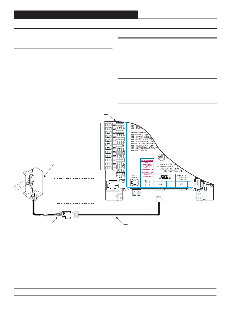
E-BUS Return Air Temperature & Humidity Sensor Wiring
E-BUS Return Air Temperature &
Humidity Sensor
The OE265-17-A E-BUS Return Air Temperature & Humidity
Sensor connects to the VCC-X Controller. A 50 foot EBC E-BUS
cable (provided) plugs into the Sensor’s attached 3 foot cable and
then plugs into the E-BUS port of the VCC-X Controller or other
E-BUS Expansion Board. The sensor should be mounted in the
upright position as shown in an area that is protected from the
elements and direct sunlight. See Figure 18 below for details.
CAUTION:
Be sure to mount the Return Air Temperature
& Humidity Sensor in an area that is not exposed
to direct sunlight. The shaded area under the
HVAC unit rain hood is normally a good
location. Unused conduit opening(s) must
have closure plugs installed and must be coated
with sealing compound to provide a rain-tight
seal. Water can damage the sensor.
NOTE:
If using multiple E-BUS Sensors or Modules, the
E-BUS Hub (HZ-EBC-248 or MS000248) or
E-BUS Adapter Board (OE365-15-EBA) may be
required.
Figure 18: OE265-17-A – E-BUS Return Air Temperature & Humidity Sensor Wiring
OE265-17-A
E-BUS Return Air
Temperature
& Humidity Sensor
50 Foot EBC E-BUS
Cable (Provided)
EBC E-BUS Cable
with Jack
Connection
NOTE: Connect the
Sensor to the VCC-X
Controller Using the
Provided EBC E-BUS
Cable.
VCC-X Controller
37X04
1.2
1.6
<PC>
4 3 2 1
3M