Overview, Parts and descriptions, 13 vcc-x controller technical guide – Orion System VCC-X Controller User Manual
Page 13
OVERVIEW
13
VCC-X Controller Technical Guide
PART NO.
PART DESCRIPTION
ILLUSTRATION
PAGE NO.
OE377-26-
00059
MHGRV-X Controller
The
MHGRV-X Controller
controls a Modulating Hot Gas Reheat Valve to
maintain a desired Supply Air Temperature and Dehumidifi cation setpoint.
The MHGRV-X Controller connects to the VCC-X Controller via an EBC
E-BUS cable. Available only from AAON.
Page 46
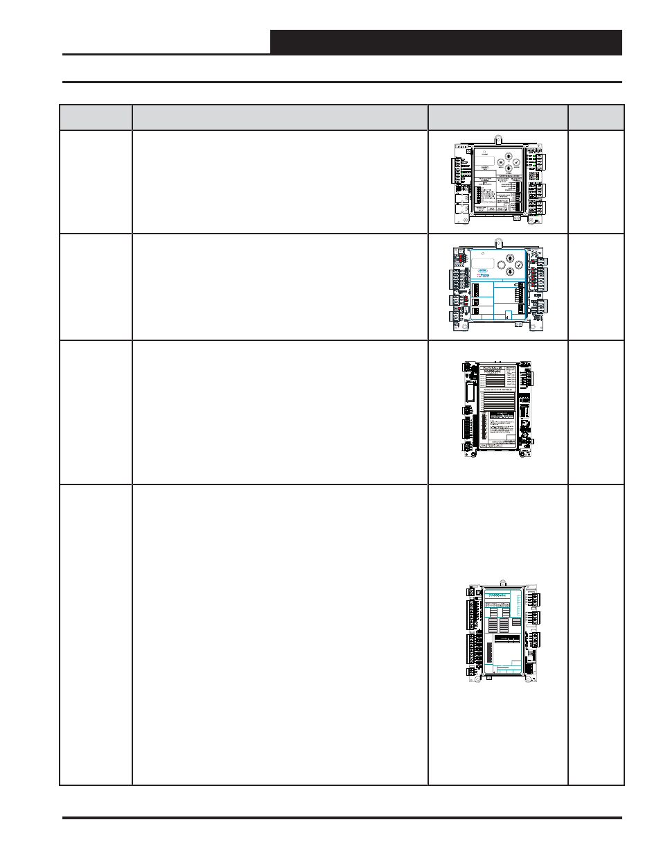
OE377-26-
00061
PREHEAT-X Controller
The PREHEAT-X Controller is designed to control fi xed stages of Preheat
and optional modulating Preheat to maintain a desired Preheat Leaving Air
Temperature Setpoint. The PREHEAT-X Controller directly connects to the
VCC-X Controller or indirectly using an E-BUS Expansion Board via an
EBC E-BUS cable.
M
ENTER
UP
DOWN
ALARM
MENU
ALARM CONTACT
HEAT 1
HEAT 2
HEAT 3
HEAT 4
HEAT 5
HEAT 6
RLY COMM
HEAT
OUTPUTS
ANALOG
OUTPUTS
0-10V MOD. SCR
GND
PWM +
PWM -
OE377-26-00061 PREHEAT-X
AAON No.: V48510
WattMaster Label
#LB102XXX-A
Rev.: 1A
E-BUS
CONNECT
E-BUS
CONNECT
LAT1
0-10V RESET
LAT2
OAT
GND
GND
ANALOG INPUTS
BINARY INPUTS
RS-485 COMM
+2
4
V
AC
GND
www.orioncontrols.com
www.aaon.com
ENABLE
T(-)
EMERG. SHUTDOWN
SHLD
FUTURE USE
R(+)
CONTACT RATING IS
1 AMP MAX
@ 24 VAC
M
ENTER
UP
DOWN
ALARM
MENU
ALARM CONTACT
HEAT 1
HEAT 2
HEAT 3
HEAT 4
HEAT 5
HEAT 6
RLY COMM
HEAT
OUTPUTS
ANALOG
OUTPUTS
0-10V MOD. SCR
GND
PWM +
PWM -
OE377-26-00061 PREHEAT-X
AAON No.: V48510
WattMaster Label
Rev.: 1D
#S
000062
W
E-BUS
CONNECT
E-BUS
CONNECT
LAT1
0-10V RESET
LAT2
EAT
GND
GND
ANALOG INPUTS
BINARY INPUTS
RS-485 COMM
+24 V
A
C
GND
www.aaon.com
ENABLE
T(-)
EMERG. SHUTDOWN
SHLD
FUTURE USE
R(+)
CONTACT RATING IS
1 AMP MAX
@ 24 VAC
www.orioncontrols.com
MSTP
BACnet
Page 48
OE332-23-
GPCX
GPC-X Controller
The GPC-X Controller provides the fl exibility to control, schedule, and/or
monitor equipment such as unit heaters, exhaust fans, motorized louvers,
etc. The GPC-X has (6) confi gurable inputs which will accept signals from
thermistor temperature sensors, 4-20mA or 0-5 VDC transmitters, or dry
contact closures. An additional modular input is provided for connection
of an OE271 Static Pressure Sensor. The GPC-X has (5) relay outputs for
on/off control and (2) analog outputs. The GPC-X also has (5) separate
2-events-per-day schedules, each with its own optimal start functions
built in. In addition, the GPC-X provides Lead/Lag start capabilities. Use
the GPC-X to provide additional schedules for your controllers. Includes:
OE332-23-GPCX Controller.
See GPC-X
Technical
Guide
OE338-23-
GPCXP
GPC-XP Controller
The GPC-XP Controller is used for controlling equipment or processes
that cannot be controlled using a standard HVAC controller. Prism 2 com-
puter front end software is used to interface with the GPC-XP
Controller functions. The GPC-XP Controller provides the fl exibility to
control, schedule, and/or monitor equipment such as unit heaters, exhaust
fans, motorized louvers, and other mechanical equipment. In addition, the
GPC-XP provides Lead/Lag start capabilities.
The GPC-XP has 8 confi gurable analog inputs which will accept signals
from thermistor temperature sensors, 4-20mA or 0-5VDC or 0-10VDC
transmitters. Custom formulas created by available math functions and
operators can be used in conjunction with the analog inputs to create a
calculated value to be used and displayed for a specifi c analog input.
The inputs are set for the desired scaling by means of a jumper bar. An
additional input is available for communicating sensors available from
WattMaster Controls. The GPC-XP also supports 8 wet contact binary
inputs which can be confi gured for either normally open or normally
closed operation. The GPC-XP has 8 relay outputs for on/off control and
4 analog outputs for proportional control signals. Highest/lowest/average
of the analog input values can be used in the GPC-XP logic or broadcast
to other controllers on the control system loop. The GPC-XP also has 8
separate 2 events per day schedules which can be assigned to any input
or output for operational control or alarm recognition based on time of day.
These schedules can also be confi gured to broadcast to other WattMaster
HVAC equipment installed on the control system loop. Includes: OE338-
23-GPCXP Controller.
See GPC-
XP Technical
Guide
Parts and Descriptions
CO
M
F
R
O
M
G
ND
CUT
TO
IS
O
L
A
T
E
WATTMASTER CONTROLS
YS102432 REV 3
LOOP COMM
GND
+24V
+5V
OUTPUTS
ADDRESS
ADD
1
2
4
8
16
32
POWER
EBUS
STATUS2
STATUS1
OUTPUTS
ANALOG
SERIAL #
OUTPUTS
RELAY
SH
R+
T-
BIN8
BIN7
BIN6
BIN5
BIN4
BIN3
BIN2
BIN1
BINARY
INPUTS
INPUTS
ANALOG
0-5
v
0-10
v
4-
2
0
m
A
AO
UT
1
-2
C14
R109
TB8
U19
U17
TB7
TB6
TB4
TB3
TB2
TB1
SW1
R97
R74
R6
1
R59
R5
5
R51
R47
R4
3
R4
1
R3
8
R21
R16
R14
D13
D12
D10
D9
D8
D7
D6
C46
C36
C21
RLY1
RLY2
RLY3
RLY4
COMMON
MADE IN USA
RLY1
RLY2
RLY3
RLY4
COMMON
AOUT1
AOUT2
AOUT3
AOUT4
GND
GND
1002
1002
.1uF
.1uF
AO
UT
3
-4
GND
1002
1002
1002
1002
1002
1002
1002
1002
1002
1002
1002
1002
.1uF
.01uF
L
OOP
BAU
D
1
2
AI7
AI8
AI6
AI5
AI4
AI1
AI2
AI3
GND
GND
GND
GND
AI8
AI7
AI6
AI5
AI4
AI3
AI2
AI1
TH
E
R
M
VDC
300
300
300
300
300
300
300
300
COM
COM
COM
COM
D11
CONNEC
ON BOA
COMMLI
RELAY CONTACT
RATING IS 1 AMP
MAX @ 24 VAC
RS-485 COMMUNICATION LOOP. WIRE
“R” TO “R”, “T” TO “T” “SHLD” TO “SHLD”
RELAY 2
RELAY 6
RELAY 1
RELAY 5
RLY 1 =
VDC
OUTPUTS
AI1 =
+ 24 VDC
+ 5 VDC
GND
BI1 =
AO1 =
AI2 =
BI2 =
AO2 =
AI3 =
BI3 =
AO3 =
AI4 =
BI4 =
AO4 =
AI5 =
BI5 =
AI6 =
BI6 =
AI7 =
BI7 =
AI8 =
BI8 =
RLY 2 =
RLY 5 =
RLY 3 =
RLY 6 =
RLY 4 =
RLY 7 =
RLY 8 =
RELAY 3
RELAY 7
RELAY 4
RELAY 8
COMMON
COMMON
USB
PORT
E-BUS
PORT
NOTES:
1.) ANALOG INPUT JUMPER SETTINGS MUST BE
SET FOR YOUR SPECIFIC INPUT DEVICE
REQUIREMENT.
2.) IT IS RECOMMENDED THAT YOU WRITE THE
DESCRIPTION OF THE INPUT, AND/OR
OUTPUTS YOU ARE CONNECTING TO THE
CONTROLLER IN THE BOXES PROVIDED ABOVE
USING A PERMANENT MARKER (SHARPIE) FOR
FUTURE REFERENCE.
®
24 VAC POWER ONLY
WARNING! POLARITY MUST BE OBSERVED
OR THE CONTROLLER WILL BE DAMAGED
www.wattmaster.com
AI1
AI2
AI3
AI4
AI5
AI6
AI7
AI8
THE
R
M
4-20
mA
0-
10
V
0-
5V
ANALOG
INPUT
JUMPERS
LED BLINK CODES
LED NAME
STATUS1
STATUS2
NORMAL OPERATION
0
1
SCHEDULE OVERRIDE
0
2
OE338-23-GPC-XP
GPC-XP CONTROLLER
WattMaster Label
#LB102095
Rev.: 1C
+2
4
VA
C
GND