Appendix c - rsmv lcd screens, Vcc-x controller technical guide, Setpoint status screens – Orion System VCC-X Controller User Manual
Page 91: Alarms screens
VCC-X Controller Technical Guide
APPENDIX C - RSMV LCD SCREENS
91
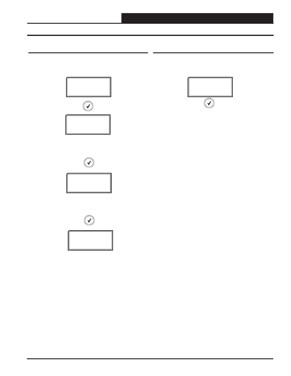
SUPERHEAT SETPOINT SETTING
Valid range is 1 to 30 degrees. Default is 15 degrees.
SPRHT SP
15
Setpoint Status Screens & Alarms Screen & Alarm History
Setpoint Status Screens
Refer to the following map when navigating through the Setpoint
Status Screens. From the SETPOINT STATUS Screen, press
<ENTER> to scroll through the screens.
SETPOINT
STATUS
HEADPR SP
340 PSI
HEAD PRESSURE SETPOINT
Valid range is 275 to 475 PSI. Default is 340 PSI.
COILT SP
40
COIL TEMPERATURE SETPOINT SETTING
Valid range is 35 to 70 degrees. Default is 40 degrees.
Alarms Screens
If an alarm is present, the ALARM LED above the LCD display will
light up red and blink. The Alarms will display and scroll automatically
from the ALARMS screen when alarms are present.
ALARMS
The alarms are as follows:
NO ALARMS:
This will be shown if there are no current alarms.
NO SUCTION PRESSURE SENSOR (SUCT) DETECTED:
This alarm indicates the Suction Pressure Sensor is not detected by
the system. This alarm will cause the system to shut down. The system
will shut down due to Unsafe Suction safety. The system will reset at
the next system startup.
HIGH HEAD PRESSURE (HP) DETECTED:
This indicates a
High Head Pressure Alarm condition which is activated when the Head
Pressure rises above 550 PSIG. This will cause the condenser to go to
100%.
NO HEAD PRESSURE SENSOR (HEAD) DETECTED:
This
alarm indicates the Head Pressure Sensor is not detected by the
system. This alarm will cause the system to shut down. The system will
reset at the next system startup.
COIL TEMP A1 FAILURE:
This alarm will occur if the coil tempera-
ture is not within operable range (below -32F or above 310F). This
could be the result of a bad sensor or faulty wiring. This alarm will shut
down the system. The system will reset at the next system startup.
COIL TEMP A2 FAILURE:
This alarm will occur if the coil tempera-
ture is not within operable range (below -32F or above 310F). This
could be the result of a bad sensor or faulty wiring. This alarm will shut
down the system. The system will reset at the next system startup.
COMPRESSOR (COMP) A1 FAILURE:
This alarm will occur if
the compressor fails to run 45 seconds after the relay is activated. This
alarm will send notifi cation to the Main Controller for staging and an
alarm and will shut down the compressor (relay) until the unit goes to
off/vent mode.
COMPRESSOR (COMP) A2 FAILURE:
This alarm will occur if
the compressor fails to run 45 seconds after the relay is activated. This
alarm will send notifi cation to the Main Controller for staging and an
alarm and will shut down the compressor (relay) until the unit goes to
off/vent mode.
LOW SUPERHEAT 1 (SH1) DETECTED:
This alarm will be
activated when the Superheat is less than 4 degrees for 2 minutes
during normal operation or for 4 minutes during the fi rst 10 minutes.
The system will shut down. This alarm will disable when the Superheat
rises above 0 degrees.
LOW SUPERHEAT 2 (SH2) DETECTED:
This alarm will be
activated when the Superheat is less than 4 degrees for 2 minutes
during normal operation or for 4 minutes during the fi rst 10 minutes.
The system will shut down. This alarm will disable when the Superheat
rises above 0 degrees.