Vcc-x controller wiring, Wall-mounted e-bus co, Sensor wiring – Orion System VCC-X Controller User Manual
Page 23: Vcc-x controller technical guide, E-bus co, Wall-mounted sensor
VCC-X Controller Technical Guide
VCC-X CONTROLLER WIRING
23
OE256-05
E-BUS Wall-Mounted
CO Sensor
2
E-BUS Cable
(EBC Cable)
E-BUS Cable
(EBC Cable)
Display
Override
OVERRIDE
ALARM
Note: Mount Both
Sensors At Least
5 Feet Above Floor.
The E-BUS Digital
Room Sensor
Connects To The
E-BUS
Sensor.
CO
2
VCC-X Controller
OE217-02,
OE217-03, or OE217-04
E-BUS Digital Room Sensor
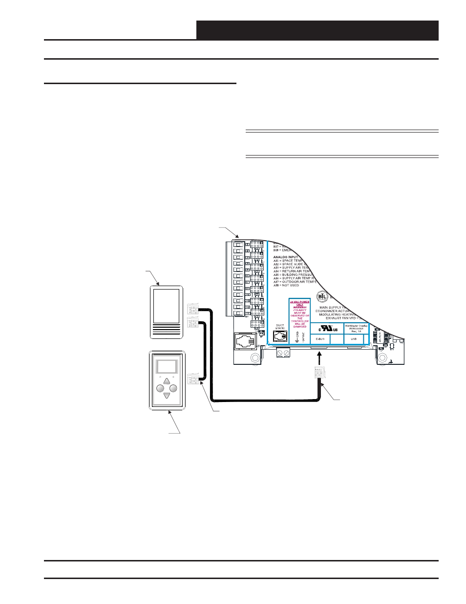
Figure 9: OE256-05 – Wall Mounted
E-BUS CO
2
Sensor Wiring
E-BUS CO
2
Wall-Mounted Sensor
The OE256-05 Wall Mounted E-BUS CO
2
Sensor is used to monitor
CO
2
levels in the space served by the HVAC unit. The E-BUS CO
2
Sensor connects to the VCC-X Controller with an EBC E-BUS
cable. It can be daisy-chained with the E-BUS Digital Room Sensor
( OE217-02, OE217-03, OE217-04) for applications requiring both
a room CO
2
sensor and room temperature sensor.
Wall-Mounted E-BUS CO
2
Sensor Wiring
It should be mounted at approximately 5 Ft. above the fl oor on
the wall in an area that does not have drafts or is exposed to direct
sunlight. See Figure 9 for wiring details and installation notes. A
Duct Mounted E-BUS CO
2
Sensor can be used if desired instead
of the Wall Mounted E-BUS CO
2
Sensor. See Figure 10 for Duct
Mounted E-BUS CO
2
Sensor wiring details.
NOTE:
If using multiple E-BUS Sensors or Modules, the
E-BUS Hub or Adapter Board may be required.