Troubleshooting, Rsmv led diagnostics, Vcc-x controller technical guide – Orion System VCC-X Controller User Manual
Page 73: Using rsmv leds to verify operation
VCC-X Controller Technical Guide
TROUBLESHOOTING
73
RSMV LED Diagnostics
Using RSMV LEDs To Verify Operation
The RSMV is equipped with LEDs that can be used to verify operation
and perform troubleshooting. There are LEDs for communication,
operation modes, and diagnostic codes. See Figure 35 for the LED
locations. The LEDs associated with these inputs and outputs allow
you to see what is active without using a voltmeter. The LEDs and
their uses are as follows:
Diagnostic LEDs
STATUS
- If the software is running, this LED should blink at a rate
of 1 blink per second.
ALARM (on board)
- If the module does not receive communications
for more than 1 minute, this LED will light up, the relays will turn
off, and the Analog Outputs will go to 0 VDC.
ALARM (above LCD display)
This red LED will light up and stay
lit when there is an alarm present. The type of alarm will display on
the LCD display. The ALARM LED also blinks when the expansion
valve is initializing at startup.
COMM
- Every time the module receives a valid E-BUS request
from the VCC-X Controller, this LED will blink on and then off,
signifying that it received a valid request and responded.
POWER
- This LED will light up to indicate that 24 VAC power has
been applied to the controller.
Binary Input LEDs
BIN1
- This green LED will light up when Compressor Status 1
contact is closed.
BIN2
- This green LED will light up when Compressor Status 2
switch is closed.
BIN3
- This green LED will light up when the Outside Coil
Temperature switch is closed.
Stepper Motor Valve LEDs
EXV-1
- This green LED will light up when Expansion Valve 1 is
modulating.
EXV-2
- This green LED will light up when Expansion Valve 2 is
modulating.
Relay LEDs
RLY1
- RLY4 - These green LEDs will light up when the relays are
enabled and will stay lit as long as they are active.
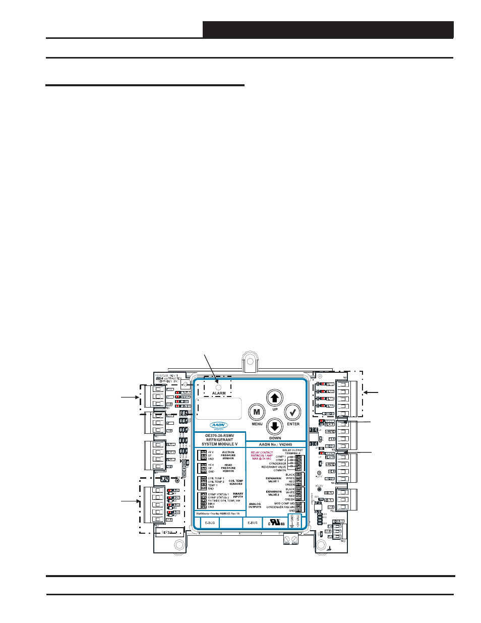
Figure 35: RSMV LED Locations
RSMV
BINARY
INPUT
LEDs
EXV-1
LED
STATUS
ALARM
COMM
POWER
LEDs
RELAY
LEDs
ALARM
LED
EXV-2
LED