Overview, Parts and descriptions, 8 vcc-x controller technical guide – Orion System VCC-X Controller User Manual
Page 8: Part no. part description illustration page no, Override alarm
OVERVIEW
8
VCC-X Controller Technical Guide
Parts and Descriptions
PART NO.
PART DESCRIPTION
ILLUSTRATION
PAGE NO.
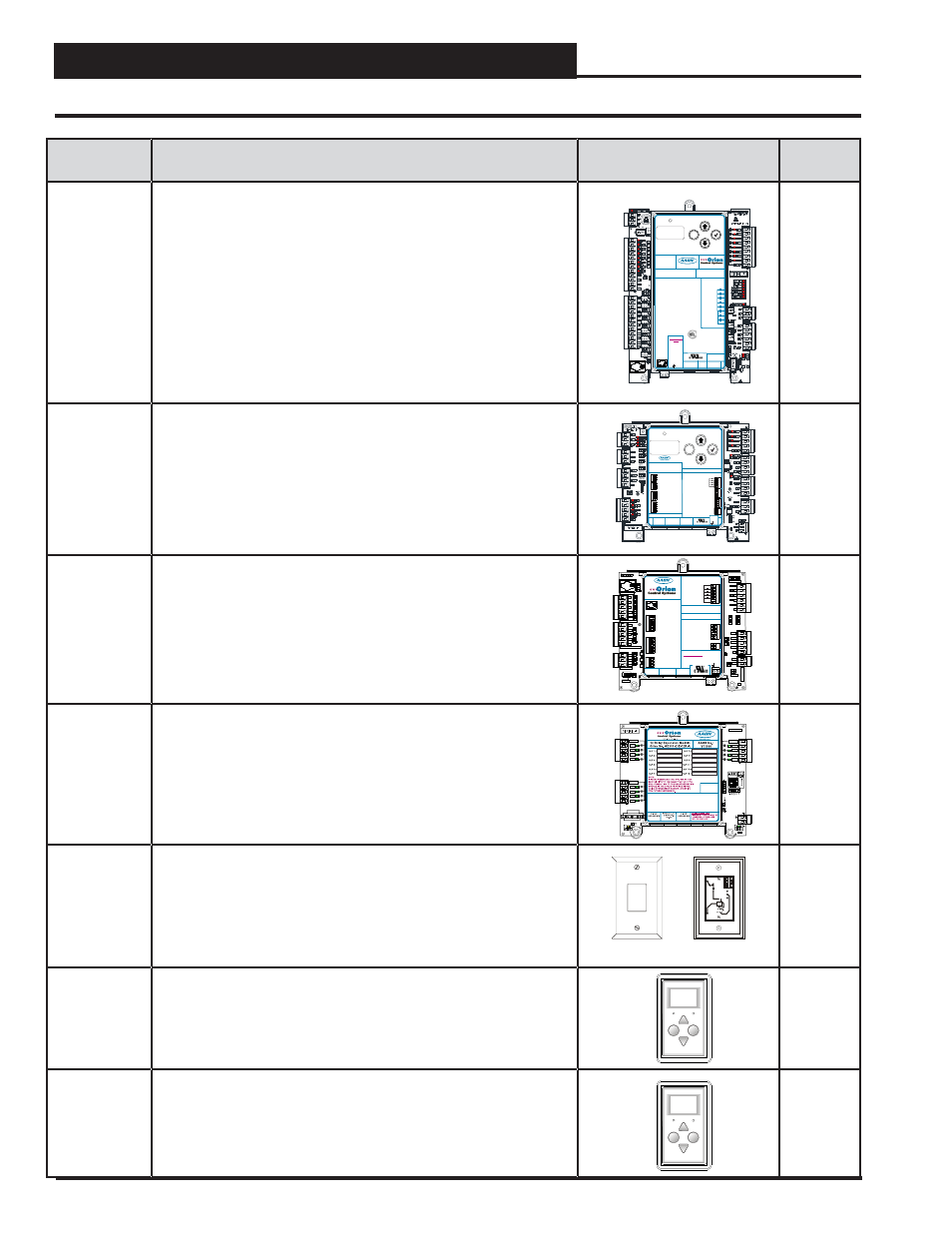
OE338-26B-
VCCX
VCC-X Controller
The VCC-X Controller provides 8 analog inputs, 4 analog outputs, 8 binary
inputs, and 8 relay outputs. It also has an on-board BACnet port for
connection to an MS/TP network. The Controller contains a 2 x 8 LCD
character display and 4 buttons that allow for status and alarm display as
well as BACnet confi guration. It presently allows for the addition of the Re-
frigerant System Module for VFD Compressors (RSMV), EM1 Expansion
Module, and the 12 Relay E-BUS Expansion Module described below.
NOTE:
Set-up, programming, and monitoring of the VCC-X Controller re-
quires one of the following communication interfaces—Prism 2 Front-End
Software used with a personal computer, System Manager Touch Screen
II, Modular System Manager SD, or Modular Service Tool SD.
Pages
14, 20-21
OE370-26-
RSMV
Refrigerant System Module for VFD Compressors
The Refrigerant System Module for VFD Compressors (RSMV) monitors
and controls one tandem compressor refrigeration circuit of the HVAC
unit. The module is designed for R410-A refrigerant. Up to 4 RSMV’s can
be connected, depending on the size of the system. There are 2 E-BUS
Expansion Ports which allow the use of communicating sensors and the
E-BUS Modules. The RSMV provides 4 analog inputs, 3 binary inputs, 3
relays, and 4 analog outputs. It connects with an EBC E-BUS cable to the
VCC-X Controller.
M
ENTER
UP
DOWN
ALARM
MENU
OE370-26-RSMV
REFRIGERANT
SYSTEM MODULE V
AAON No.: V42440
E-BUS
E-BUS
+24
V
AC
GND
RELAY CONTACT
RATING IS 1 AMP
MAX @ 24 VAC
CONDENSER
COMP 1
COMP 2
EXPANSION
VALVE 1
SUCTION
PRESSURE
SENSOR
HEAD
PRESSURE
SENSOR
COIL TEMP
SENSORS
BINARY
INPUTS
EXPANSION
VALVE 2
ANALOG
OUTPUTS
BLACK
+5 V
+5 V
COIL TEMP 1
COMP STATUS 1
BLACK
MOD COMP SIG
CONDENSER FAN SIG
WHITE
SP
HP
COIL TEMP 2
COMP
2
STATUS
GND
GND
TEMP 3
OUTSIDE COIL TEMP. SW
BIN 4
GND
GND
WHITE
RED
RED
GND
GREEN
GREEN
REVERSING VALVE
COMMON
RELAY OUTPUT
TERMINALS
www.aaon.com
WattMaster Overlay #000065 Rev 1A
SW
Pages
15, 38
OE336-
23-VCCXEM1
VCC-X EM1 Expansion Module
The EM1 Expansion Module adds Title 24 Economizer Feedback and
Chilled Water applications. It also provides 2 analog outputs for controlling
a Return Air Bypass Damper and a Return Damper in Return Air Bypass
applications. It also has 5 confi gurable relay outputs. It connects with an
EBC E-BUS cable to the VCC-X Controller.
Pages
16, 40
OE358-23E-
12R-A
12 Relay E-BUS Expansion Module
The 12 Relay Expansion Module adds 12 confi gurable relays to the
VCC-X Control System. It connects to the VCC-X Controller with an EBC
E-BUS cable.
Pages
17, 44
OE210
OE211
OE212
OE213
Standard Room Sensor–Plain, w/Override, w/Override &
Slide Adjust & w/Slide Adjust Only
Includes: Standard Room Sensor - Plain, with Override, with Override and
Slide Adjust & with Slide Adjust only. For wall mounting. Use with VCC-X
Controller only. Connects to controller via fi eld fabricated wiring.
TMP
GND
AUX
OUT
Page 25
OE217-02
E-BUS Digital Room Sensor - Temp. Only
LCD Display and keypad allow for setpoint adjustment, override, and
display of certain status and setpoints. The OE217-02 is used with the
VCC-X Controller for room air temperature sensing applications. Uses
EBC E-BUS cable.
Display
Override
OVERRIDE
ALARM
Page 22
OE217-03
E-BUS Digital Room Sensor - Temp and Humidity
LCD Display and keypad allow for setpoint adjustment, override, and
display of certain status and setpoints. The OE217-03 is used with the
VCC-X Controller for room air temperature and humidity sensing applica-
tions. Uses EBC E-BUS cable.
Display
Override
OVERRIDE
ALARM
Page 22
M
ENTER
UP
DOWN
ALARM
MENU
RELAY CONTACT
RATING IS 1 AMP
MAX @ 24 VAC
RS-485 COMM
LOOP. WIRE
“R” TO “R”,
“T” TO “T”
“SHLD” TO “SHLD”
24 VAC POWER
ONLY
WARNING!
POLARITY
MUST BE
OBSERVED OR
THE
CONTROLLER
WILL BE
DAMAGED
www.aaon.com
www.orioncontrols.com
VCC-X CONTROLLER
Orion No.: OE338-26B-VCCX
AAON No.: V42430
BINARY INPUTS
BI1= PROOF OF AIRFLOW
BI2
BI3
BI5
BI6
AI1
AI2
AI3
AI4
AI5
AI6
= DIRTY FILTER
= HOOD ON/OFF
= REMOTE OCCUPIED
= REMOTE COOLING
= REMOTE HEATING
= REMOTE DEHUMIDIFICATION
= EMERGENCY SHUTDOWN
= SPACE TEMPERATURE
= SPACE SLIDE OFFSET
= SUPPLY AIR TEMPERATURE
= RETURN AIR TEMPERATURE
= BUILDING PRESSURE
= SUPPLY AIR TEMP RESET
= OUTDOOR AIR TEMPERATURE
= NOT USED
BI4
BI7
BI8
AI7
AI8
ANALOG INPUTS
WattMaster Overlay
#S
000064
Rev.: 1A
W
E-BUS
USB
+24
VAC
GND
MAIN FAN
RELAY 2
RELAY 3
RELAY 4
RELAY 5
RELAY 6
RELAY 7
RELAY 8
RELAY
COMMON
MAIN SUPPLY FAN VFD =
ECONOMIZER ACTUATOR =
MODULATING HEATING =
EXHAUST FAN VFD =
AO1
AO2
AO3
AO4
BACNET–
BACNET SHIELD
BACNET +
=
T
=
SH
=
R
DUCT
STATIC
RLY9
RLY10
RLY11
RLY12
RLY-COM
MADE IN USA
RLY-COM
RLY-COM
RLY1
RLY2
RLY3
RLY4
RLY8
RLY7
RLY6
RLY5
24VAC
GND
EXPANSION BOARD
YS102324 REV 2
RELAY
WattMaster Label
#L 102196-A
Rev.: 1A
B
+24
VAC
GND
RELA
Y
CONT
ACT
RA
TING IS 1
AMP
MAX @ 24 V
AC
R1
R2
R3
R4
R5
RC
RELAY OUTPUT
TERMINALS
ANALOG OUTPUT TERMINALS
GND
RETURN DAMPER
RETURN BYPASS
CHILLED WATER
AOUT4
T1
T2
ECON FEEDBACK
GND
SIG 2
+5V
BIN 1
PWM –
SIG 1
BIN 2
PWM +
GND
BIN 3
GND
GND
E-BUS
CONNECT
E-BUS
CONNECT
24 VAC POWER ONLY
WARNING! POLARITY
MUST BE OBSERVED OR
THE CONTROLLER WILL
BE DAMAGED
POWER INPUT TERMINAL BLOCK
BINARY INPUT TERMINALS
PRESSURE SENSOR INPUT
TERMINALS
TEMPERATURE SENSOR INPUT
TERMINALS
www.aaon.com
www.orioncontrols.com
VCC-X Expansion Module 1
Orion No.: OE336-23-VCCXEM1
NOT USED
AAON No.: V53990
5.
VREF
BIN3
BIN2
BIN1
2
1
ON
ADDRESS
BINARY INPUTS
PRESSURE SENSOR INPUTS
GND
GND
+5V
SIG2
SIG1
TEMP SENSOR INPUTS
GND
GND
T3
T2
T1
STATIC PRESSURE
TB1
R58
J2
D29
D28
D27
TB2
P1
D26
D25
D24
TB7
R22
R21
R19
R18
R16
R15
R1
R1
R10
R6
R3
R1
D18
D15
D12
D8
D4
D1
C8
C6
C5
C4
C3
C2
COMM
STAT
ALARM
PWR
PWM-
GND
R5
R4
R3
R2
R1
SERIAL
#
TB3
TB9
TB6
R6
1
R5
7
R5
6
R
5
4
R5
3
R4
9
R4
8
R4
6
R4
5
Q6
D2
1
D2
0
D1
9
D1
7
C2
4
2
1
Rc
R35
R31
R29
R24
D13
D11
D10
D9
PWM+
R9
AOUT1
AOUT2
AOUT3
AOUT4
56
2
1
OF
F
1002
1002
1002
1002
1002
1002
47
4992
1002
1004
1002
1002
1004
1
002
300
300
10uF
10uF
10uF
10uF
10uF
10uF
.01uF
10u
F
300
1002
1002
3650
R4
1002
R5
1002
J1
C26
OPTIONS
R2
47
47
10
0
1
10
0
1
3650
3650
3650
56
2
1
56
2
1
56
2
1
56
2
1
YS102482 REV1