Inputs & outputs, Vcc-x controller & rsmv module input/output maps, Vcc-x controller technical guide 50 – Orion System VCC-X Controller User Manual
Page 50: Input/output map
Zone
Zone
INPUTS & OUTPUTS
VCC-X Controller Technical Guide
50
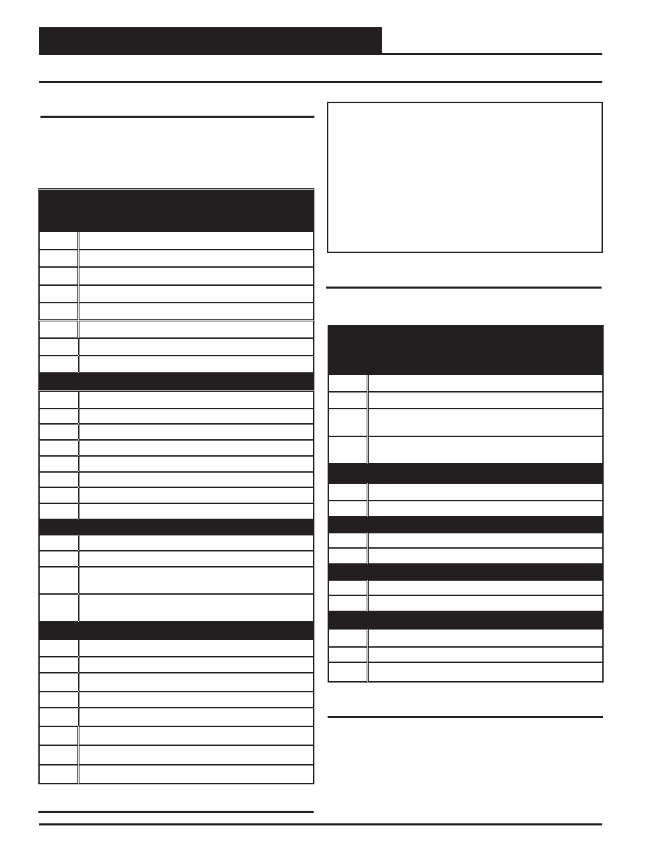
VCC-X Controller & RSMV Module Input/Output Maps
Input/Output Map
See Table 2 for the VCC-X Controller’s Input/Outputs, Table 3 for
the Refrigeration System Module for VFD Compressor’s Inputs/
Outputs, and Table 4 for the VCC-X EM1 Expansion Module’s
Inputs/Outputs.
VCC-X CONTROLLER
Analog Inputs
1
Space Temperature (AI1)
2
Space Slide Offset (AI2)
3
Supply Air Temperature (AI3)
4
Return Air Temperature (AI4)
5
Building Pressure (AI5)
6
Supply Air Temperature Reset (AI6)
7
Outside Air Temperature (AI7)
8
Static Pressure (Phone Jack)
Binary Inputs
1
Proof of Flow (BIN1)
2
Dirty Filter (BIN2)
3
Hood On/Off (BIN3)
4
Remote Forced Occupied (BIN4)
5
Remote Forced Cooling (BIN5)
6
Remote Forced Heating (BIN6)
7
Remote Forced Dehumidifi cation (BIN7)
8
Emergency Shutdown (BIN8)
Analog Outputs (0-10 VDC)
1
Main Supply Fan VFD (AOUT1)
2
Economizer (Outdoor Air Damper) (AOUT2)
3
Modulating Heating (Hot Water, Steam, or SCR)
(AOUT3)
4
Exhaust Fan VFD / Building Pressure Control
Signal (AOUT4)
Binary Outputs (24 VAC)
1
Fan Relay (RLY1)
2
Confi gurable Relay (RLY2)
3
Confi gurable Relay (RLY3)
4
Confi gurable Relay (RLY4)
5
Confi gurable Relay (RLY5)
6
Confi gurable Relay (RLY6)
7
Confi gurable Relay (RLY7)
8
Confi gurable Relay (RLY8)
Table 2: VCC-X Controller Inputs & Outputs
NOTE:
The following E-BUS sensors and modules are avail-
able to connect to the VCC-X Controller via E-BUS ports or
E-BUS Expansion Modules:
1. E-BUS Digital Room Sensor - LCD Display - Temp Only or
Temp & Humidity
2. E-BUS Digital Room Sensor - No LCD Display - Temp &
Humidity
3. E-BUS Space and Return Air CO
2
Sensors
4. E-BUS connection to EBTRON, GreenTrol and Paragon
Air Flow Stations
5. E-BUS Outside Air Temperature & Humidity Sensor
Table 3: RSMV Inputs & Outputs
REFRIGERATION SYSTEM MODULE
FOR VFD COMPRESSORS
Analog Inputs
1
Suction Pressure Sensor (SP)
2
Head Pressure Sensor (HP)
3
Coil (Suction Line) Temperature Sensor 1
(TEMP1)
4
Coil (Suction Line) Temperature Sensor 2
(TEMP2)
Binary Inputs
1
Compressor Status 1 (BIN1)
2
Compressor Status 2 (BIN2)
Analog Outputs (0-10 VDC)
1
Modulating Compressor (AOUT1)
2
Condenser Fan Signal (AOUT2)
Stepper Motor Outputs
1
Expansion Valve 1 (EXV-1)
2
Expansion Valve 2 (EXV-2)
Binary Outputs (24 VAC)
1
Compressor 1 Enable Relay (R1)
2
Compressor 2 Enable Relay (R2)
3
Condenser Enable Relay (R3)
Table 2, cont.: VCC-X Controller Inputs & Outputs