5 installation/start-up, 2 selecting the installation location – KACO Powador XP100-HV User Manual
Page 14
Page 14
Operating Instructions Powador XP100-HV
I n s t a l l a t i o n / S t a r t - u p
5 Installation/Start-up
5.1
Transporting the unit to the installation location
Once it has arrived at the installation location, the inverter may be transported using the designated eyebolts only.
These are located on the top of the inverter housing (fi gure 5).
CAUTION
Impact hazard, risk of breakage to the inverter
The centre of gravity is located in the upper part of the inverter.
›
Transport the inverter in an upright position.
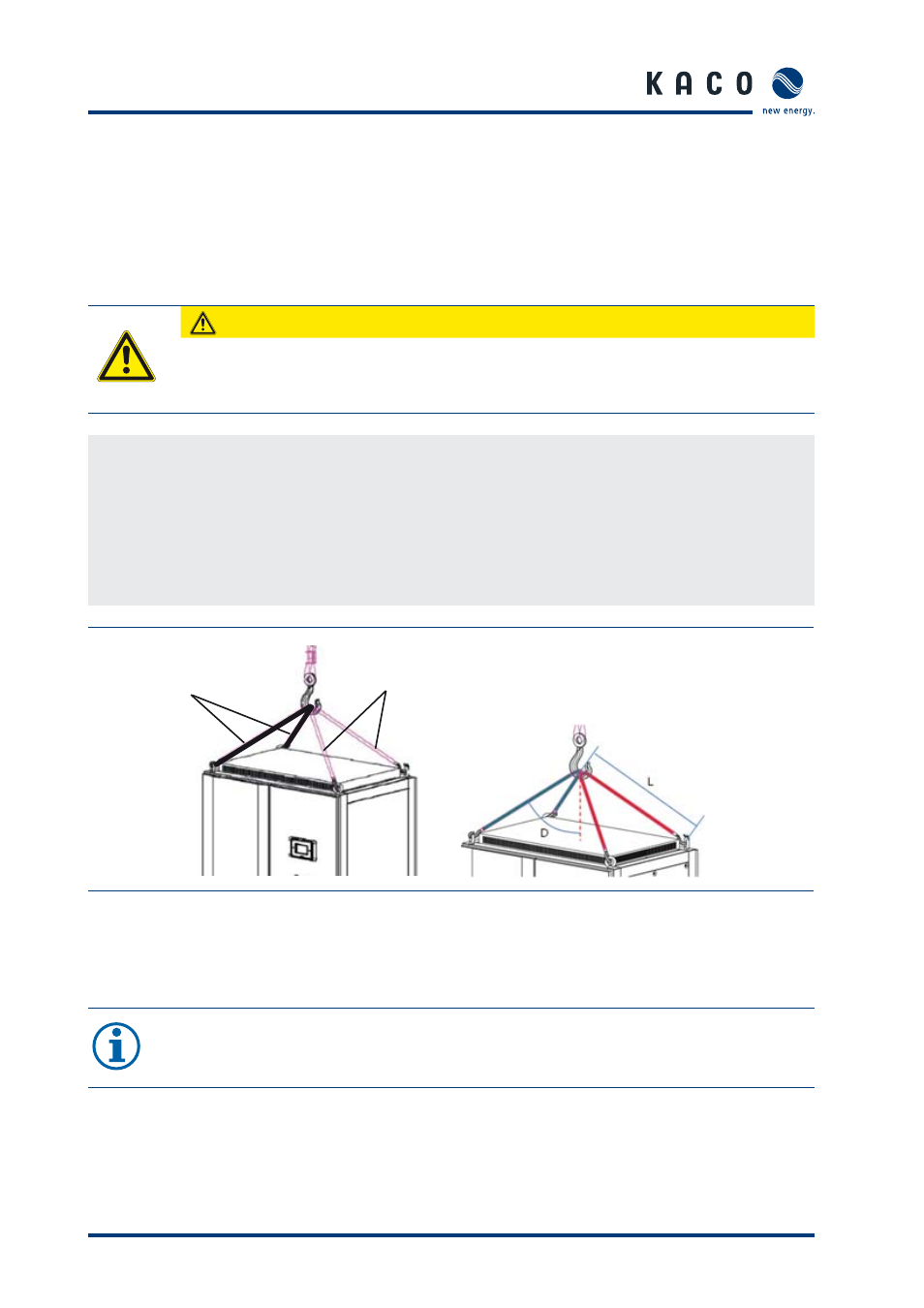
Transporting the inverter
Transport the inverter in an upright position.
Attach a rope (1) to the two eyebolts on the right.
Attach a second rope (2) to the two eyebolts on the left.
Attach both ropes to a hook, making sure that the ropes do not cross each other.
Position the hook at the middle of the unit.
Figure 5: Transporting the unit at the installation location
5.2
Selecting the installation location
NOTE
The maximum fl ow rate of the cooling air is 2590 m³ per hour (fi gure 6).
Please keep this value in mind when you select the installation location.
2
1
›
Angle ( D ) - 50°
›
Length ( L ) - 950mm