4 analogue input, 1 solar sensor – KACO Powador XP100-HV User Manual
Page 86
Page 86
Operating Instructions Powador XP100-HV
U s e r i n t e r f a c e
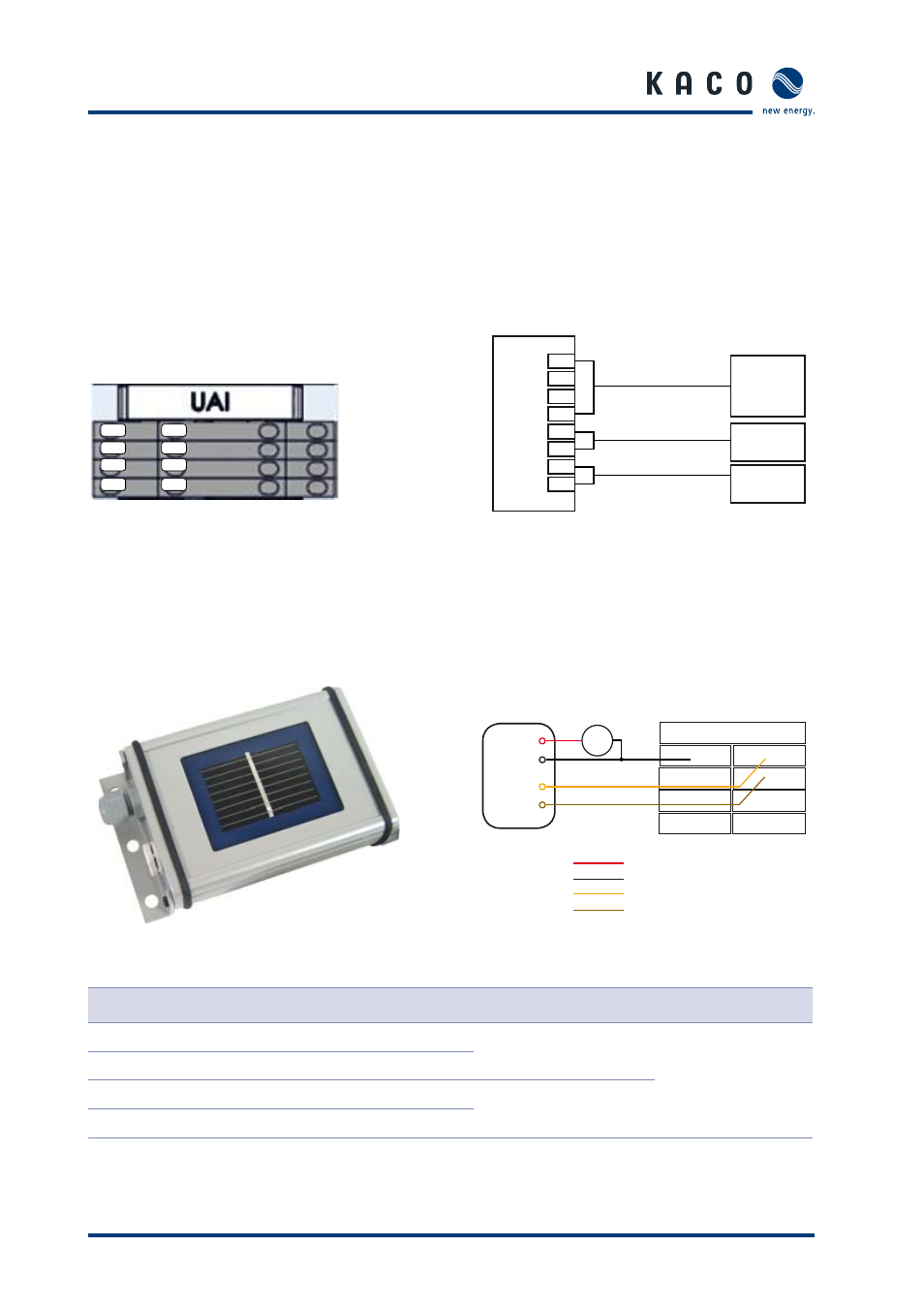
9.4 Analogue
Input
The inverter has four analogue connections.
1a - 2b
Solar sensor
3a - 3b
Ambient temperature sensor
4a - 4b
Wind speed sensor
Input range
0 to 10 V
Figure 83: Analogue user input
Figure 84: Connection diagram of the analogue
interface
9.4.1 Solar
sensor
Figure 85: Si-12TC solar sensor
Figure 86: Connection diagram for solar sensor
Terminal number
Terminal designation
Specifi cation
Wire cross- section
1a
IVN
0 to 10 V
AWG 24
(0.205 mm
2
)
1b
IVP
2a
CTN
0 to 10 V
2b
CTP
Table 27: Connections for analogue user input – solar sensor
1a
2a
3a
4a
1b
2b
3b
4b
1a
2a
3a
4a
1b
2b
3b
4b
An
a
lo
g
u
e
input
Wind
speed
Solar
sensor
PT1000
1b
1b
1a
UAI
2a
2a
2b
2b
3a
3a
3b
3b
4a
4a
4b
4b
Si-12TC
og
bn
Red (rd)
Black (bk)
Orange (og)
Brown (bn)
VCC (12 to 24 Vdc)
GND
Irradiation (0 to 10 V)
Cell Temperature (0 to 10 V)
12 ... 24 Vdc
+
-
rd
bk