3 rs485 interface – KACO Powador XP100-HV User Manual
Page 84
Page 84
Operating Instructions Powador XP100-HV
U s e r i n t e r f a c e
Terminal
number
Terminal designation
Specifi cation
Wire cross-
section
4a
UDO 1B
Potential-free, common
output contact
AWG 20
(0.518 mm
2
)
4b
UDO 1A
Potential-free output contact A
5a
N/C
5b
UDO 1C
Potential-free output contact B
Table 23: Connections for digital user output
9.3 RS485
interface
The inverter has two RS485 connections.
RS485-1
Input for the Powador Argus
Interface for optional Powador-go
RS485-2
Interface for the MMI's internal data logger, or for the external Powador proLOG data logger
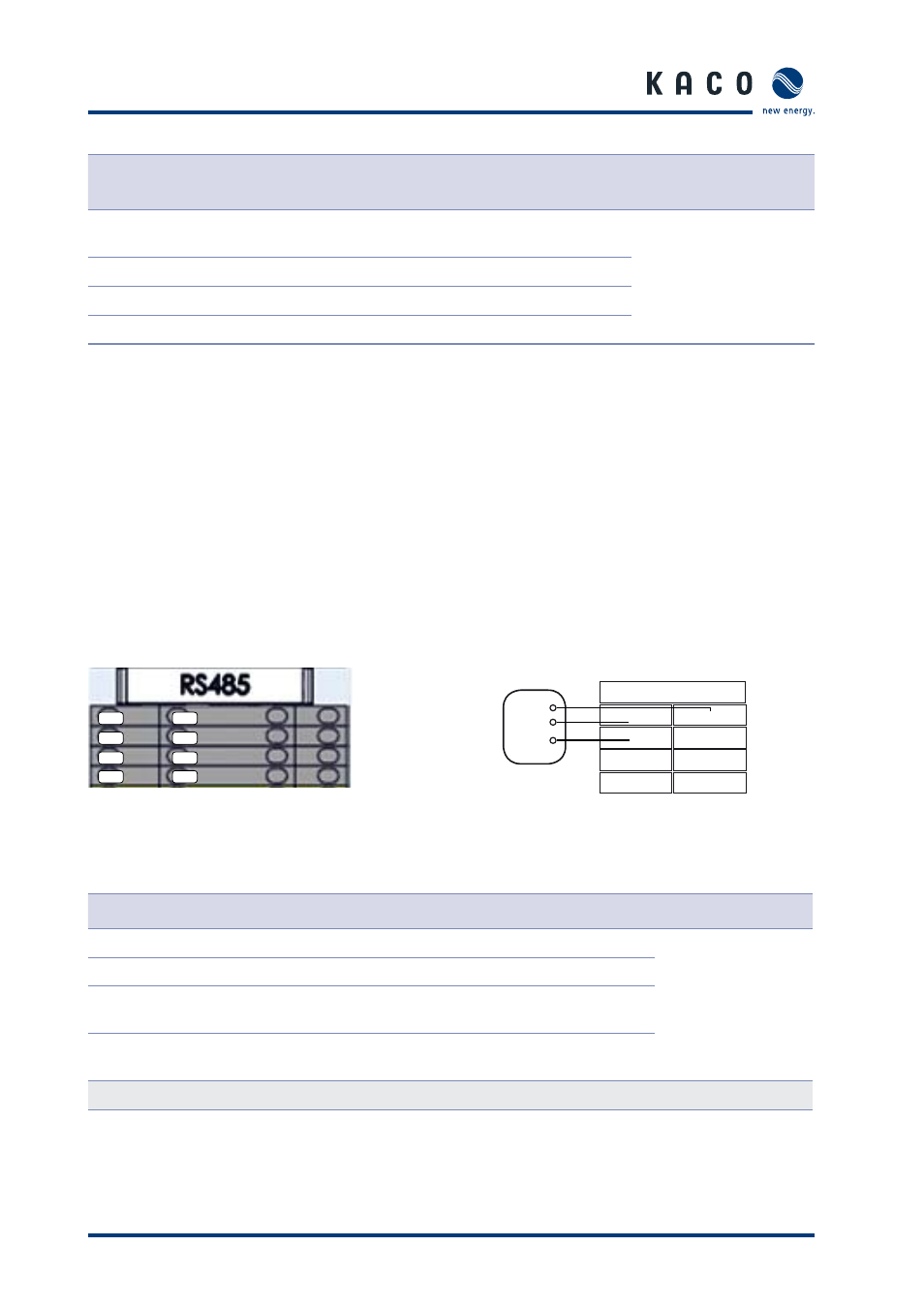
9.3.1 RS485-1
Interface
Figure 79: RS485-1 connection
Figure 80: Circuit diagram for RS485-1
connection
Terminal number
Terminal designation
Specifi cation
Wire cross- section
1a
RS485 A1
RS485 signal A1
AWG 20
(0.518 mm
2
)
1b
RS485 B1
RS485 signal B1
2a
RS485 G1
RS485 communication
GND 1
2b
RS485 C1
Terminal of termination
resistor
In order to install a terminating resistor, connect a wire to terminals RS485 A1 (1a) and RS485 C1 (2b).
Table 24: Connections for RS485-1
1b
1b
1a
RS485
2a
2a
2b
2b
3a
3a
3b
3b
4a
4a
4b
4b
Signal transceiver
B
A
GND
1a
2a
3a
4a
1b
2b
3b
4b