3 settings for rs485 interfaces – KACO Powador XP100-HV User Manual
Page 85
Operating Instructions Powador XP100-HV
Page 85
U s e r i n t e r f a c e
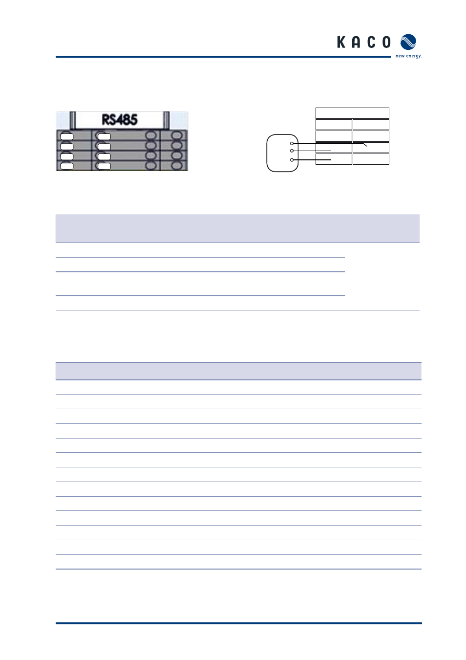
9.3.2 RS485-2
Interface
Figure 81: RS485-2 connection
Figure 82: Circuit diagram for RS485-2
connection
Terminal number
Terminal designation
Specifi cation
Wire cross-
section
3a
RS485 A2
RS485 signal A2
AWG 20
(0.75 mm
2
)
3b
RS485 B2
RS485 signal B2
4a
RS485 G2
RS485 data transmission
GND 2
4b
RS485 C2
Table 25: Connections for RS485-2
9.3.3
Settings for RS485 interfaces
ID
Name
Unit
Default value
Min.
Max.
0
Activate Powador-proLOG
OFF
OFF
ON
1
MMI address
0
0
31
2
Change Powador-go address
-
-
-
3
Activate Powador-go
OFF
OFF
ON
4
Diff . tolerance
%
10
10
100
5
Fault trigger time
minutes
120
10
240
6
Address 0 string number
0
0
4
7
Address 1 string number
0
0
4
8
Address 2 string number
0
0
4
..
..
0
0
4
..
..
0
0
4
36
Address 30 string number
0
0
4
37
Address 31 string number
0
0
4
Table 26: RS485 interface settings
1b
1b
1a
RS485
2a
2a
2b
2b
3a
3a
3b
3b
4a
4a
4b
4b
Signal transceiver
B
A
GND
1a
2a
3a
4a
1b
2b
3b
4b