Trigger system summary – AMETEK BPS Series Programming Manual User Manual
Page 164
Advertising
AMETEK Programmable Power
BPS / MX / RS Series SCPI Programming Manual
164
Manual P/N 7003-961 Rev AA
6.8
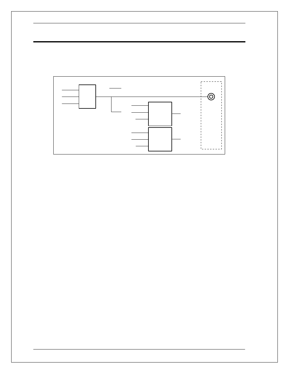
Trigger System Summary
Figure 6-5 shows a functional block diagram of the AC/DC source’s trigger system. If both
trigger systems are initiated at the same time, the Acquisition trigger system will respond to
the first trigger generated while the transient trigger system will respond to the second
trigger. Thus, the acquisition has the highest priority.
BOT
EOT
LIST
OUTP:TTLT:SOUR
TRIGGER
SOURCE
BUS
TTLT
PHASE
ACQUISITION
TIRGGER
SYSTEM
IMM
BUS
PHASE
TRANSIENT
TRIGGER
SYSTEM
TRIG:ACQ:SOUR
TRIG:TRAN:SOUR
MEASUREMENT
TRIGGER
OUTPUT
TRIGGER
OFF
ON
TRIGGER
OUT
Function
Strobe
OUTP:TTLT:STAT
Figure 6-5: Trigger system block diagram
Advertising
This manual is related to the following products: