Hypertherm Powermax30 XP Service Manual User Manual
Page 106
106
Powermax30 XP Service Manual 808150 Revision 1
6 – Power Supply Component Replacement
7. Press the new power switch into the new panel with the ON (I) label at the top of the switch.
You should hear the switch snap into place.
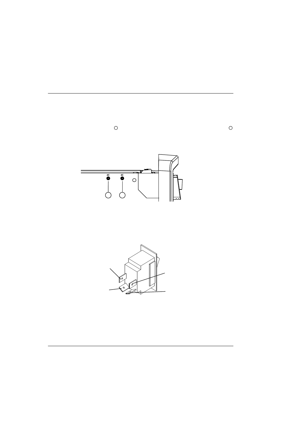
8. Push the connectors for the two white wires that are attached to the power board at “AC” onto the bottom two pins
of the power switch. The left “AC” wire
connects to the bottom-left pin on the power switch; the right “AC” wire
connects to the bottom-right pin on the power switch. See
Figure 42
9. Press the connector for the black (CSA) or brown (CE/CCC) wire onto the pin on the upper left side of the power
switch.
10. Press the connector for the white (CSA) or blue (CE/CCC) wire onto the pin on the upper right side of the power
switch.
Figure 43
11. Reconnect the ground wire to the ground wire clip on the rear panel.
12. Complete the following procedures:
a. See Install the component barrier on page 91.
b. See Install the power supply cover on page 89.
c. Reconnect the gas supply and power cord, and set the power switch to ON (I).
1
2
AC
AC
1
2
White (AC) (left pin)
Black (CSA)
Brown (CE/CCC)
White (AC) (right pin)
White (CSA)
Blue (CE/CCC)