Reset led – Hypertherm Powermax30 XP Service Manual User Manual
Page 70
70
Powermax30 XP Service Manual 808150 Revision 1
5 – Troubleshooting and System Tests
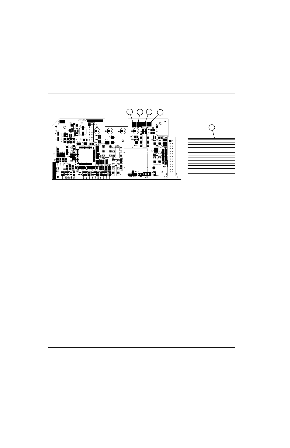
Figure 10
During normal operation, the power-ON LED on the front of the power supply and the Start and Transfer LEDs on the
control board illuminate. When a problem occurs with the system, one or more of the fault LEDs on the front of the power
supply and the Error LED or the Reset LED on the control board may illuminate or blink.
Use the control board Error and Reset LEDs to troubleshoot
The Reset and Error LEDs provide information to use when troubleshooting a system failure. If the LEDs on the front of
the power supply are blinking, count the number of times the Error LED blinks. Then, look at the following table to
determine the corrective action.
Reset LED
When the control board’s Reset LED illuminates, the voltages on the power board may be incorrect. Perform the following
tests at J7 on the power board. (See
Test 2 – power board voltage checks on page 76.)
Test pin 5 to ground for 3.3 VDC (±10%).
Test pin 7 to ground for 5 VDC (±10%).
Test pin 12 to ground for 2.2 VDC (±10%).
If the values you find are not within ±10% of the three values listed above, detach the control board’s ribbon cable and
perform the tests again. If you find the correct values the second time, replace the control board. (See
control board on page 107.) Otherwise, replace the power board. (See Remove the power board on page 109.)
1
2
3
4
5
1
Reset/watchdog
2
Error
3
Transfer (XFR)
4
Start
5
Ribbon cable