11 gpio, 1 connections (mk2), 2 connections (mk4) – Nevion Multicon User Manual
Page 70
Hardware Information
70
ID: man-multicon
Multicon Manual Rev. L
12.11 GPIO
The GPI output can be used for wiring up alarms for third party control systems. The GPI output
will be active, if one or more alarms are active in the local Flashlink system.
The GPI inputs can be used for triggering alarms in Multicon. The alarms can also send SNMP
traps and are shown in the alarms list. These inputs can be given custom labels.
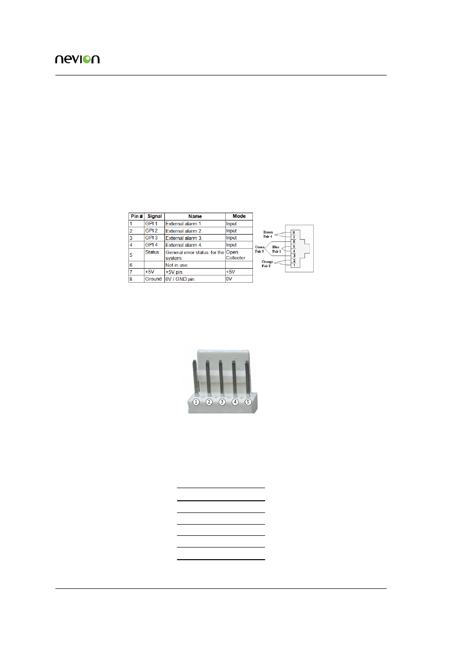
12.11.1 Connections (mk2)
The GPI connector is shown in
. The GPI output is an open collector output, sinking
to ground when an alarm is triggered.
Figure 12.11
GPIO pin out
12.11.2 Connections (mk4)
The GPI connectors are KK 5 pins.
Figure 12.12
GPIO pinout
GPI inputs uses internal pull-up to 3,3V.
GPI outputs uses open collector transistor, sinking to ground when an alarm is triggered. Max
voltage is 30V and max current is 100 mA.
Table 12.4
GPIO pinout
Pin GPI IN
GPI OUT
1
Ground (0V) Ground (0V)
2
Input 1
Output 1
3
Input 2
Not used
4
Input 3
Not used
5
Input 4
Not used