12 monitor flashlink power supplies (mk2), 13 serial connectivity – Nevion Multicon User Manual
Page 71
Hardware Information
71
ID: man-multicon
Multicon Manual Rev. L
12.12 Monitor Flashlink Power Supplies (mk2)
It is possible to monitor the Flashlink power supply via Multicon and receive alarms if there is a
power failure.
You can monitor the power supply status via the GPI on Multicon backplane. You will have to
make a cable and connect this from the relay pins on the DC INPUT/OUTPUT (DC1, DC2) (DB9)
connector.
With this cable you can see the alarm status both in the Multicon web interface and using an SNMP
Manager. Note that in Multicon you can maximum get 4 GPI alarms.
If you would like Multicon to send the GPI alarms to a SNMP Manager you have to configure the
SNMP trap destination under the CONFIG tab and SNMP setup. Put the IP address of the SNMP
Manager under SNMP trap destination.
How-to make the cable:
1. From power 1 (DC1, frame 1): Pin 1 from RJ45, soldered to pin 3 on DB9. Pin 8 from RJ45,
soldered to pin 7 on DB9.
2. From power 2 (DC2, frame 1): Pin 2 from RJ45, soldered to pin 3 on DB9. Pin 8 from RJ45,
soldered to pin 7 on DB9.
3. From power 1 (DC1, frame 2): Pin 3 from RJ45, soldered to pin 3 on DB9. Pin 8 from RJ45,
soldered to pin 7 on DB9.
4. From power 2 (DC2, frame 2): Pin 4 from RJ45, soldered to pin 3 on DB9. Pin 8 from RJ45,
soldered to pin 7 on DB9.
Additional info:
See above for more information GPI connections on the Multicon back-plane and page the FR-
2RU-10-2 manual for pin-out on DC1 and DC2.
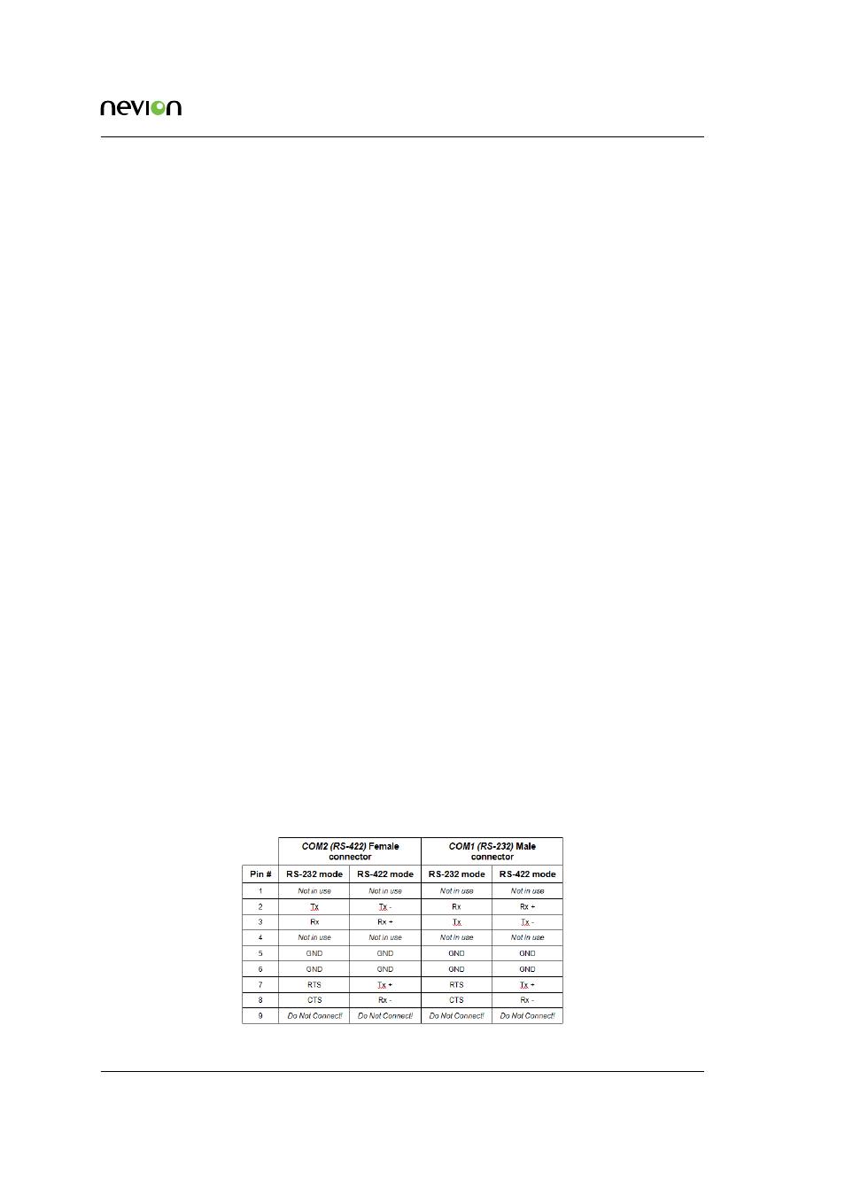
12.13 Serial Connectivity
Connection can be made through the serial port(s) of Multicon; see also the note below for con-
nection details.
The communication parameters are configurable. Please refer to the protocol documentation of
the appropriate communication/control protocol.
The DB9 connectors for the serial port(s) of the router have the following pin-out: