Front panel indicators and controls, Figure 1.1, Fms 2u front panel indicators and controls – RLE FMS V.1.13 User Manual
Page 18
18
FMS User Guide
800.518.1519
1
System Overview
1.3.
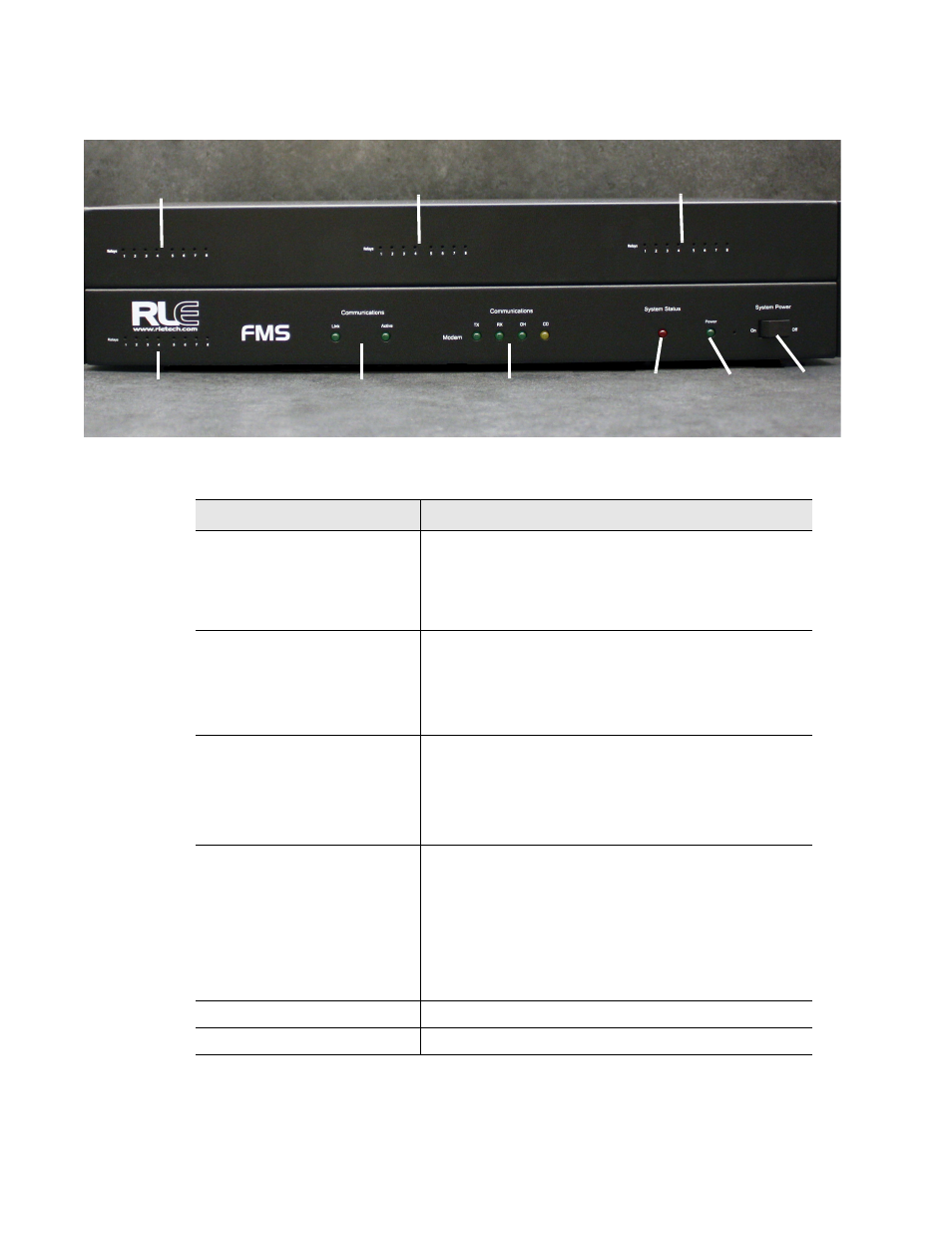
Front Panel Indicators and Controls
Figure 1.1
FMS 2U Front Panel Indicators and Controls
Status
LEDs
Status
LEDs
Network
Modem
Expansion Card #1
Status LEDs
Expansion Card #2
Status LEDs
Expansion Card #3
Status LEDs
Expansion Card #4
Status LEDs
Status
LEDs
System
LED
Power
Power
Switch
System
Indicator
Description
Expansion Card Relay Status
Only available on Expansion Card A, the green LED
illuminates when the relay is active.
Expansion Card #1 LEDs are on the left hand side of
the 1U FMS enclosure. Expansion cards #2, #3, and
#4 are located across the top of the 2U FMS enclosure.
Communication
Network Status LEDs
Link – Green if network link is established. Red if there
is no connection.
Active – Illuminated green when transmitting or
receiving data.
Communication
Modem Status LEDs
TX - Green when information is being transmitted.
RX - Green when if information is being received.
OH - Green when he Modem detects a dial tone (off
hook).
CD - Yellow when if a carrier is detected.
System Status LED
Flashes red during initial boot up, approximately 30
seconds.
If the initial boot up fails, the LED continues to flash.
This indicates a condition that requires service; users
must contact RLE for more information.
After the boot up, this LED turns off if no alarms are
present, or turns solid when the unit is in an alarm
condition.
Power LED
Green when the power is on.
System Power Switch
Use this switch to turn power to the unit on and off.