Rear panel indicators, Sw1 switch settings, Rear panel indicators sw1 switch settings – RLE FMS V.1.13 User Manual
Page 21: Figure 1.3, Figure 1.4, Sw1-1 switch and sw1-2 switch
rletech.com
FMS User Guide
21
1
System Overview
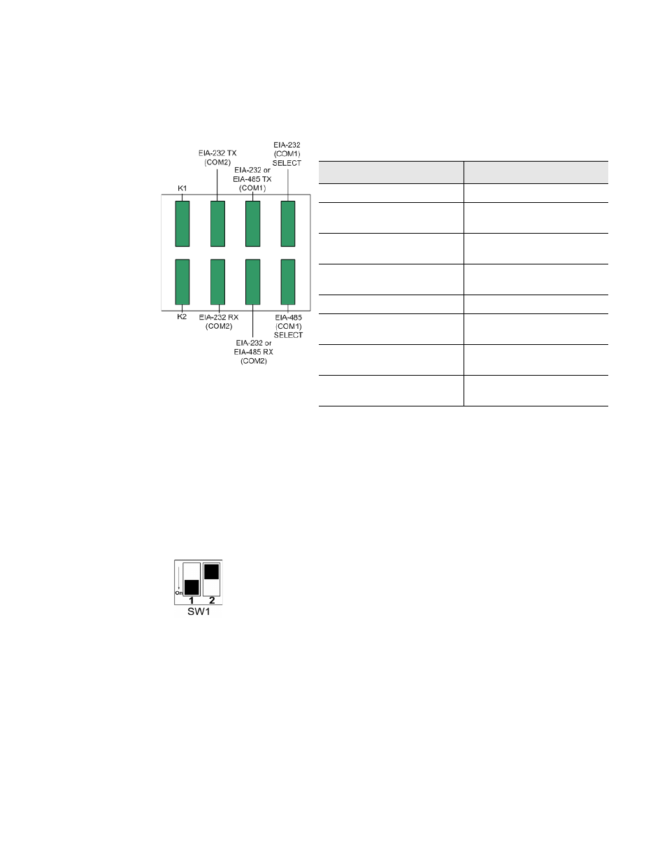
1.5. Rear
Panel
Indicators
The rear panel of the FMS houses a series of green LEDs.
The chart below tracks indicator status when the
corresponding green LED is illuminated:
Figure 1.3
Rear Panel Indicators
1.6. SW1
Switch
Settings
♦
SW1-1: EIA-485 Termination switch should be in the down position (ON) if the FMS is an
end device on an EIA-485 network.
♦
SW1-2: Reserved for future use.
Figure 1.4
SW1-1 Switch and SW1-2 Switch
SW1-1 switch is in the down position (ON) and SW1-2 switch is in the up position (OFF).
Status
Indicator
K1 (Output Relay)
Relay is energized.
EIA-232 TX (COM2)
Interface
Data is being transmitted.
EIA-232 or EIA-485 TX
(COM1) Interface
Data is being transmitted.
EIA-232 (COM1) Select
Interface
EIA-232 selected (P2)
K2 (Output Relay)
Relay is energized.
EIA-232 RX (COM2)
Interface
Data is being received.
EIA-232 or EIA-485 RX
(COM1) Interface
Data is being received.
EIA-485 (COM1) Select
Interface
EIA-485 selected (TB5)