Figure a.3, 2u fms unit - opened, Figure a.4 – RLE FMS V.1.13 User Manual
Page 181: Sw2 dip switches, Table a.2, Sw2 dip switch settings for expansion card slots
rletech.com
FMS User Guide
181
A
FMS Expansion Cards
3
Gently lift and hinge the top lid to the side and lay it next to the base (bottom chassis).
Figure A.3
2U FMS Unit - Opened
4
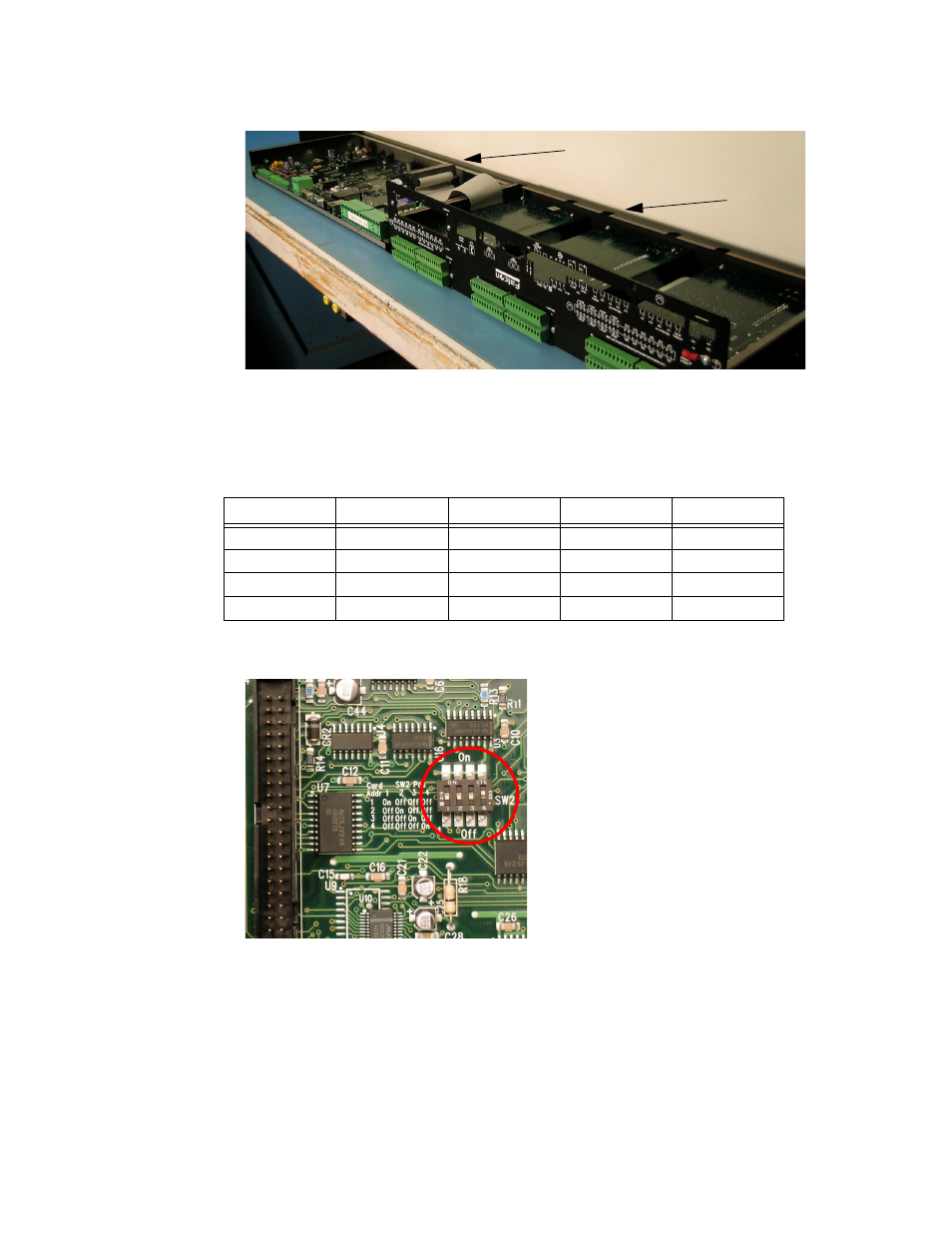
On the expansion card, set the card slot address (SW2 DIP switches) to the slot number
where the card will reside (1 through 4).
lists the position of the switches based
on the slot number.
shows the location of the DIP switches.
Figure A.4
SW2 DIP Switches
5
Now you need to mount the expansion card. The expansion card will either mount in slot 1
in the base of the unit, or in slot 2, 3, or 4, in the lid of the unit.
If the expansion card is to be mounted in the base (Slot 1):
a
Attach the ribbon cable to the card.
b
Secure the provided screw into the remaining hole.
Slot
DIP Switch 1 DIP Switch 2 DIP Switch 3 DIP Switch 4
1
On
Off
Off
Off
2
Off
On
Off
Off
3
Off
Off
On
Off
4
Off
Off
Off
On
Table A.2
SW2 DIP Switch Settings for Expansion Card Slots
Lid
Base