Terminal block designations, Figure 1.2, Fms terminal block designations – RLE FMS V.1.13 User Manual
Page 19: Table 1.1
rletech.com
FMS User Guide
19
1
System Overview
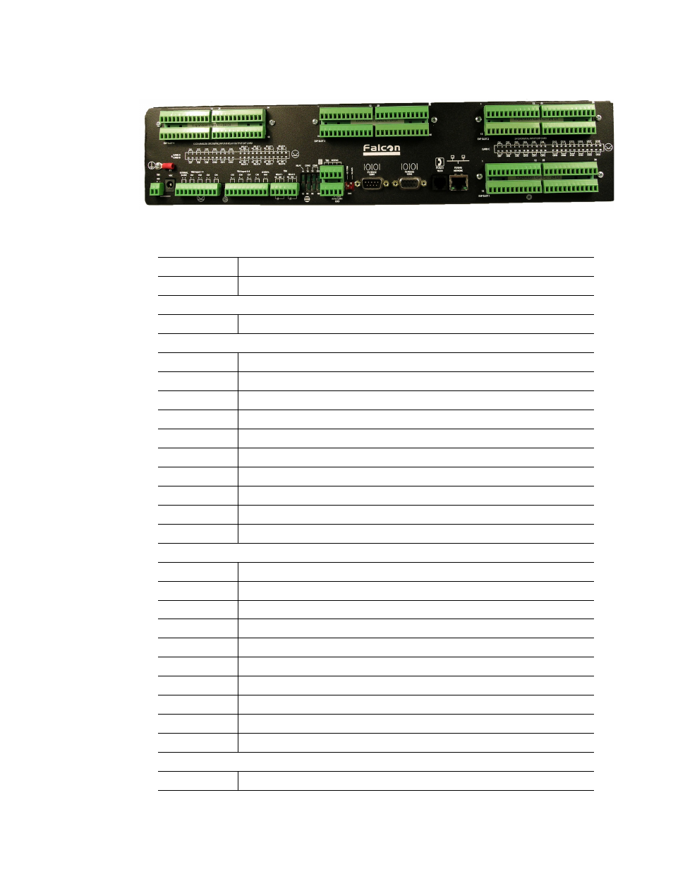
1.4.
Terminal Block Designations
Figure 1.2
FMS Terminal Block Designations
TB1-1
(+) Input for 24 or 48VDC (optional) power
TB1-2
(-) Input for 24 or 48VDC (optional) power
P1
24VDC wall adapter input (center +) (not available with 48VDC version)
TB2-1
24VDC positive (+) external output (power for sensors)
TB2-2
24VDC positive (+) external output (power for sensors)
TB2-3
Channel 1 positive (+)
TB2-4
Channel 1 negative (-)
TB2-5
Channel 2 positive (+)
TB2-6
Channel 2 negative (-)
TB2-7
Channel 3 positive (+)
TB2-8
Channel 3 negative (-)
TB2-9
Channel 4 positive (+)
TB2-10
Channel 4 negative (-)
TB3-1
Channel 5 positive (+)
TB3-2
Channel 5 negative (-)
TB3-3
Channel 6 positive (+)
TB3-4
Channel 6 negative (-)
TB3-5
Channel 7 positive (+)
TB3-6
Channel 7 negative (-)
TB3-7
Channel 8 positive (+)
TB3-8
Channel 8 negative (-)
TB3-9
24VDC ground external output (power for sensors)
TB3-10
24VDC ground external output (power for sensors)
TB4-1
Relay 1 normally closed (NC)
Table 1.1
Terminal Block Designations