3 mrpp typical scenario, Mrpp, Ypical – PLANET WGSW-50040 User Manual
Page 241: Cenario
31-12
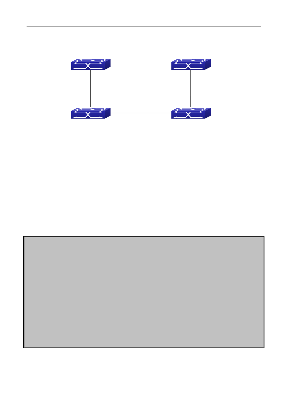
31.3 MRPP Typical Scenario
Figure
31-2 MRPP typical configuration scenario
The above topology often occurs on using MRPP protocol. The multi switch constitutes a single MRPP ring,
all of the switches only are configured an MRPP ring 4000, thereby constitutes a single MRPP ring.
In above configuration, SWITCH A configuration is primary node of MRPP ring 4000, and configures E1/1 to
primary port, E1/2 to secondary port. Other switches are secondary nodes of MRPP ring, configures primary
port and secondary port separately.
To avoid ring, it should temporarily disable one of the ports of primary node, when it enables each MRPP ring
in the whole MRPP ring; and after all of the nodes are configured, open the port.
When disable MRPP ring, it needs to insure the MRPP ring doesn’t have ring.
SWITCH A configuration Task Sequence:
Switch(Config)#mrpp enable
Switch(Config)#mrpp ring 4000
Switch(mrpp-ring-4000)#control-vlan 4000
Switch(mrpp-ring-4000)#fail-timer 18
Switch(mrpp-ring-4000)#hello-timer 5
Switch(mrpp-ring-4000)#node-mode master
Switch(mrpp-ring-4000)#enable
Switch(mrpp-ring-4000)#exit
Switch(Config)#interface ethernet 1/1
Switch(config-If-Ethernet1/1)#mrpp ring 4000 primary-port
Switch(config-If-Ethernet1/1)#interface ethernet 1/2
Switch(config-If-Ethernet1/2)#mrpp ring 4000 secondary-port
Switch(config-If-Ethernet1/2)#exit
Switch(Config)#
SWITCH A
SWITCH B
SWITCH C
SWITCH D
Master Node
MRPP Ring 4000
E1
E2
E1
E2
E1
E12
E11