PLANET WGSW-50040 User Manual
Page 77
8-4
Configuration result:
Shell prompts ports aggregated successfully after a while, now ports 1, 2, 3, 4 of Switch A form an aggregated
port named “Port-Channel1”, ports 6, 8, 9, 10 of Switch B forms an aggregated port named “Port-Channel2”;
configurations can be made in their respective aggregated port configuration mode.
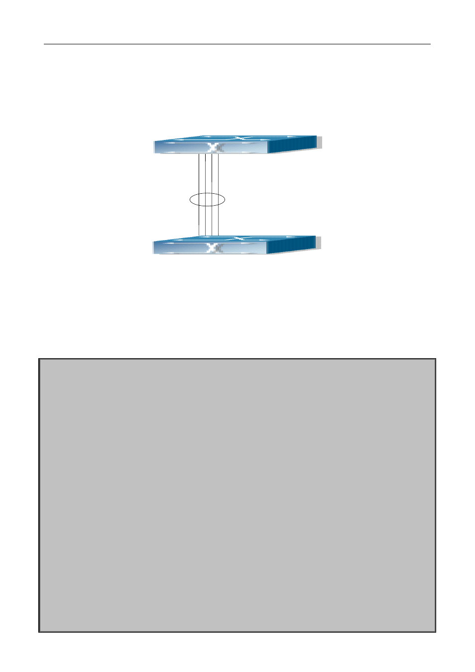
Scenario 2: Configuring Port Channel in ON mode.
Figure 8-3 Configuring Port Channel in ON mode
Example: As shown in the figure, ports 1, 2, 3, 4 of SwitchA are access ports that belong to VLAN1. Add those
four ports to group1 in “on” mode. Ports 6, 8, 9, 10 of SwitchB are access ports that also belong to VLAN1,
add these four ports to group2 in “on” mode.
The configuration steps are listed below:
SwitchA#config
SwitchA (config)#interface ethernet 1/1
SwitchA (Config-If-Ethernet1/1)#port-group 1 mode on
SwitchA (Config-If-Ethernet1/1)#exit
SwitchA (config)#interface ethernet 1/2
SwitchA (Config-If-Ethernet1/2)#port-group 1 mode on
SwitchA (Config-If-Ethernet1/2)#exit
SwitchA (config)#interface ethernet 1/3
SwitchA (Config-If-Ethernet1/3)#port-group 1 mode on
SwitchA (Config-If-Ethernet1/3)#exit
SwitchA (config)#interface ethernet 1/4
SwitchA (Config-If-Ethernet1/4)#port-group 1 mode on
SwitchA (Config-If-Ethernet1/4)#exit
SwitchB#config
SwitchB (config)#port-group 2
SwitchB (config)#interface ethernet 1/6
SwitchB (Config-If-Ethernet1/6)#port-group 2 mode on
SwitchB (Config-If-Ethernet1/6)#exit
SwitchB (config)#interface ethernet 1/8-10
SwitchB (Config-If-Port-Range)#port-group 2 mode on
SwitchA
SwitchB