PLANET WGSW-50040 User Manual
Page 29
3-12
The switch is Layer 3 switch that can be configured with several IPv4/IPv6 addresses. The following example
assumes the shipment status of the switch where only VLAN1 exists in the system. The following describes
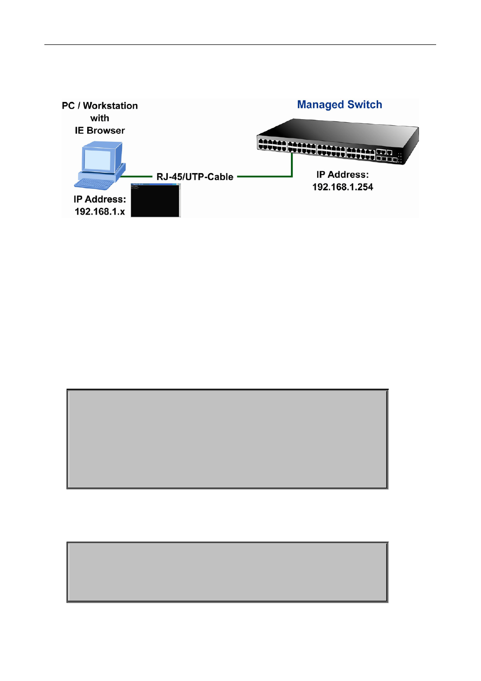
the steps for a Telnet client to connect to the switch’s VLAN1 interface by Telnet (with IPv4 address example):
Figure 3-6 Manage the switch by Telnet
Step 1: Configure the IP addresses for the switch and start the Telnet Server function on the switch.
First is the configuration of host IP address. This should be within the same network segment as the switch
VLAN1 interface IP address. Suppose the switch VLAN1 interface IP address is 10.1.128.251/24. Then, a
possible host IP address is 10.1.128.252/24. Run “ping 10.1.128.251” from the host and verify the result,
check for reasons if ping failed.
The IP address configuration commands for VLAN1 interface are listed below. Before in-band management,
the switch must be configured with an IP address by out-of-band management (i.e. Console mode), the
configuration commands are as follows (All switch configuration prompts are assumed to be “Switch”
hereafter if not otherwise specified):
Switch>
Switch>enable
Switch#config
Switch(config)#interface vlan 1
Switch(Config-if-Vlan1)#ip address 10.1.128.251 255.255.255.0
Switch(Config-if-Vlan1)#no shutdown
To enable the Telnet Server function, users should type the CLI command telnet-server enable in the global
mode as below:
Switch>en
Switch#config
Switch(config)# telnet-server enable