Altera ALTDLL User Manual
Page 12
Chapter 2: Getting Started
2–6
Design Example: Implementing Read Paths Using Stratix III Devices
© February 2012
Altera Corporation
ALTDLL and ALTDQ_DQS Megafunctions User Guide
8. On the Output Clocks tab, on the clk c0 page, specify the parameters as shown in
. You don’t have to parameterize the other pages on the Output Clocks
tab because you only use one clock for this design.
9. Click Finish.
10. Click Finish. The ALTPLL instance is generated.
11. Click OK to close the Symbol window.
12. Place the instance on the altdll_altdq_dqs_design_ex1.bdf Block Editor.
Generate the ALTDLL Megafunction
To generate the ALTDLL megafunction, perform the following steps:
1. Double-click anywhere on the Block Editor window. The Symbol window appears.
2. Click MegaWizard Plug-In Manager. Page 1 of the MegaWizard Plug-In Manager
appears.
3. Select Create a new custom megafunction variation.
4. Click Next. Page 2a of the MegaWizard Plug-In Manager appears.
5. Select Create a new custom megafunction variation.
6. Click Next. Page 2a of the MegaWizard Plug-In Manager appears. Select ALTDLL,
and Verilog HDL, and type the file name as dll_150MHz.v.
7. On the Parameter Settings tab, on the General page, specify the parameters as
shown in
. These parameters configure the general settings for the
ALTDLL instance.
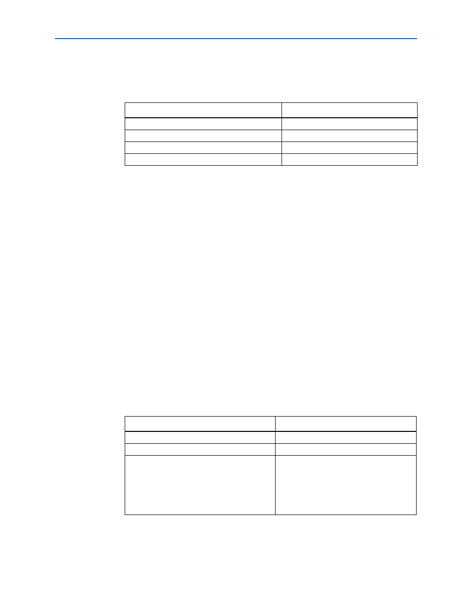
Table 2–2. ALTPLL Output Clocks/clk c0 Settings
Settings
Value
Use this clock
Turned on
Enter output clock frequency
150 Mhz
Clock phase shift
0 deg
Clock duty cycle (%)
50
Table 2–3. ALTDLL GeneraL Settings
Settings
Value
Currently selected device family
Stratix III
Match project/default
Turned on.
Number of Delay Chains
12
Refer to
chapter in the Stratix III Device Handbook, and
pick a DLL mode that supports 150 MHz and
find the DLL setting.