Altiobuf megafunction and delay chains integration – Altera ALTDLL User Manual
Page 54
Chapter 4: Functional Description
4–18
ALTIOBUF Megafunction and Delay Chains Integration
© February 2012
Altera Corporation
ALTDLL and ALTDQ_DQS Megafunctions User Guide
ALTIOBUF Megafunction and Delay Chains Integration
You must instantiate the ALTIOBUF megafunction separately to configure the input
buffer block, output buffer block, and differential output buffer block that are used
together with the ALTDQ_DQS megafunction. These I/O buffers are used so that the
impedance between the system and the external circuitry matches. This
implementation maximizes the power transfer and minimizes reflections from the
external circuitry.
c
The ALTIOBUF megafunction must not be used to configure any dynamic delay
chains. The ALTIOBUF must only be used to configure the I/O buffers to avoid
conflict between the dynamic configuration and delay chain circuitry in the
ALTDQ_DQS megafunction.
The dynamic delay chains are controlled by the configuration circuitry encapsulated
in the ALTDQ_DQS megafunction. Each instance of the I/O buffer uses the D1, D5,
and D6 delay chains. These delay chains are dynamically configured by the
IO_CONFIG
and
DQS_CONFIG
blocks. The
IO_CONFIG
and
DQS_CONFIG
blocks are
a shift registers that change the delay settings in the I/O buffers that are connected to
the I/O pins and DQ and DQS I/O pins, respectively. The
IO_CONFIG
block cannot
configure the dynamic delay chains on the OCT path or the DQS input path because
these delay chains are configured by the
DQS_CONFIG
block.
f
For more information about the
IO_CONFIG
and
DQS_CONFIG
blocks, refer to
“DQS_CONFIG / IO_CONFIG Block” on page 4–22
f
For more information about input buffer, output buffer, or bidirectional buffer, refer to
through
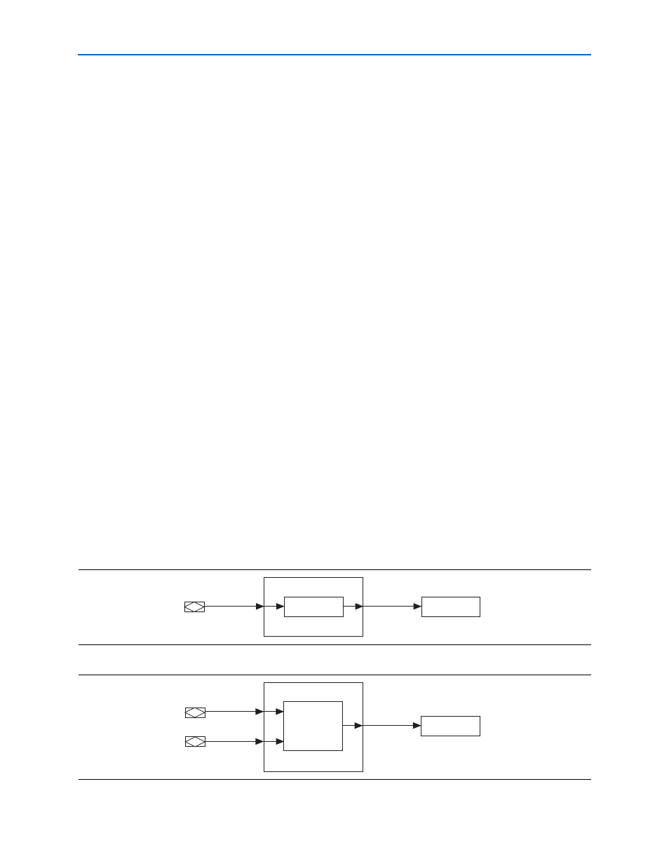
show the various configurations of the ALTDQ_DQS
megafunction when combined with the ALTIOBUF megafunction. These
configurations apply to both the DQ and DQS I/O pins. The use of the
datain
and
datout
signals in these figures are generic. These signals represent either data, clock,
or strobe in external memory interfaces.
Figure 4–10. Input Only—Single-Ended
Figure 4–11. Input Only—Differential
ALTIOBUF
ALTDQ_DQS
datain
dataout
IO_IBUF
ALTIOBUF
datain
dataout
datain_n
IO_IBUF
ALTDQ_DQS