Adding the external pll, Adding the external pll -12 – Altera 50G Interlaken MegaCore Function User Manual
Page 21
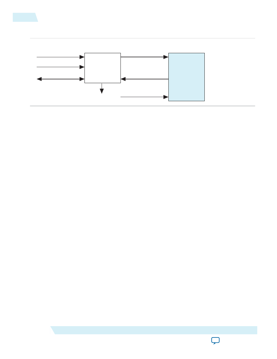
Figure 2-4: Typical Connection of Reconfiguration Controller to 50G Interlaken IP Core
50G Interlaken
MegaCore
Function
Reconfiguration
Controller
mgmt_clk_clk
mgmt_rst_reset
Avalon-MM IF
reconfig_to_xcvr
reconfig_from_xcvr
reset_n
reconfig_busy
Altera recommends that you set the Reconfiguration Controller input clock frequency in the range of 100
MHz to 125 MHz. Refer to the Altera Transceiver PHY IP Core User Guide for frequency range require‐
ments specific to the device family.
The Reconfiguration Controller reset input should be asserted high during power up and remain asserted
until its clock input becomes stable with the
mgmt_clk_locked
signal indicating a locked condition of the
clock. Upon power up, the Reconfiguration Controller asserts
reconfig_busy
output high. The
reconfig_busy
signal remains asserted until the Reconfiguration Controller completes the configuration
of all transceivers.
Related Information
•
Adding the External PLL
50G Interlaken IP core variations that target an Arria 10 device require an external transceiver PLL to
function correctly in hardware. 50G Interlaken IP core variations that target an Arria V or Stratix V
device include the transceiver PLLs and do not require that you configure any additional PLLs.
You can use the IP Catalog to generate an external PLL IP core that configures a TX PLL on the device.
• Select Arria 10 Transceiver ATX PLL, Arria 10 Transceiver CMU PLL, or Arria 10 FPLL.
• In the parameter editor, set the following parameter values:
• PLL output frequency to one half the per-lane data rate of the IP core variation. The transceiver
performs dual edge clocking, using both the rising and falling edges of the input clock from the
PLL. Therefore, this PLL output frequency setting drives the transceiver with the correct clock for
the Interlaken lanes.
• PLL reference clock frequency to a frequency at which you can drive the TX PLL input reference
clock. You must drive the external PLL reference clock input signal at the frequency you specify for
this parameter.
The number of external PLLs you must define depends on the distribution of your Interlaken TX serial
lines across physical transceiver channels. You specify the clock network to which each PLL output
connects by setting the clock network in the PLL parameter editor.
2-12
Adding the External PLL
UG-01140
2015.05.04
Altera Corporation
Getting Started With the 50G Interlaken IP Core