High level block diagram, Clocking and reset structure for ip core, High level block diagram -4 – Altera 50G Interlaken MegaCore Function User Manual
Page 30: Clocking and reset structure for ip core -4
High Level Block Diagram
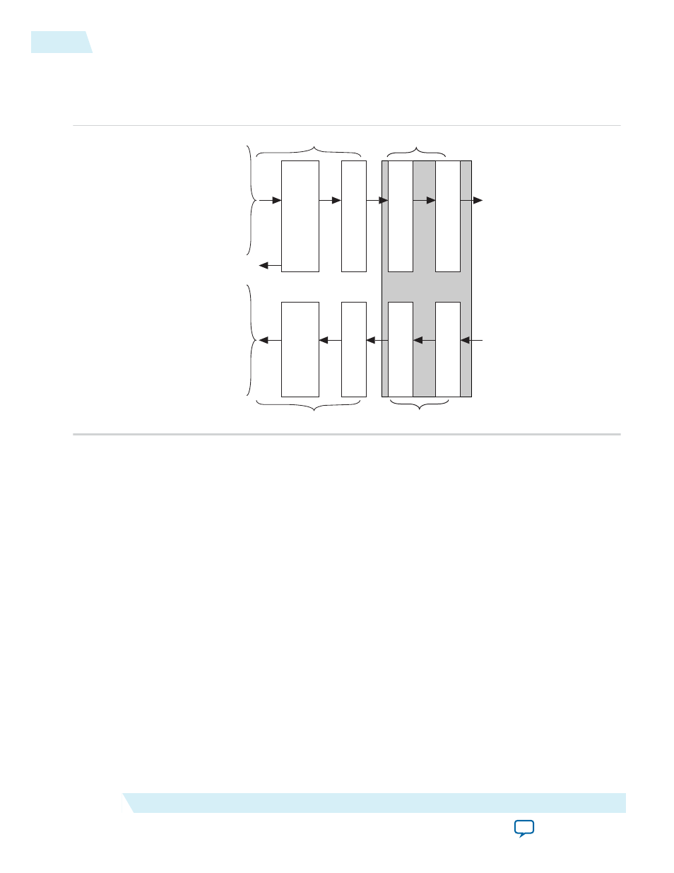
Figure 4-1: 50G Interlaken Block Diagram
irx_chan[7:0]
irx_num_valid[2:0]
irx_sob
irx_eob
irx_sop
irx_eopbits[3:0]
irx_dout_words[255:0]
irx_calendar[16 x n - 1:0]
irx_err
itx_chan[7:0]
itx_num_valid[2:0]
itx_sob
itx_eob
itx_sop
itx_eopbits[3:0]
itx_din_words[255:0]
itx_calendar[16 x n - 1:0]
Transceiver Blocks
TX
PCS
TX
PMA
TX
MAC
TX
Transmit
Buffer
tx_usr_clk
clk_tx_common
clk_rx_common
rx_usr_clk
RX
PCS
RX
PMA
RX
MAC
RX
Regroup
tx_pin[m - 1:0]
rx_pin[m - 1:0]
itx_ready
The 50G Interlaken MegaCore function consists of two paths: an Interlaken TX path and an Interlaken
RX path. Each path includes MAC, PCS, and PMA blocks. The PCS blocks are implemented in hard IP.
Related Information
•
50G Interlaken IP Core Transmit Path Blocks
For more information about the Interlaken TX path.
•
50G Interlaken IP Core Receive Path Blocks
on page 4-19
For more information about the Interlaken RX path.
Clocking and Reset Structure for IP Core
The following topics describe the clocking and reset structure of the 50G Interlaken IP core:
50G Interlaken IP Core Clock Signals
on page 4-5
on page 4-5
IP Core Reset Sequence with the Reconfiguration Controller
on page 4-7
4-4
High Level Block Diagram
UG-01140
2015.05.04
Altera Corporation
Functional Description