2 lateral control panel, right side – BINDER KBF LQC 240 User Manual
Page 19
Advertising
KBF LQC (E5.3) 07/2014
page 19/114
2.2 Lateral control panel, right side
(3)
(4)
(5)
(6)
(9)
(7)
(8)
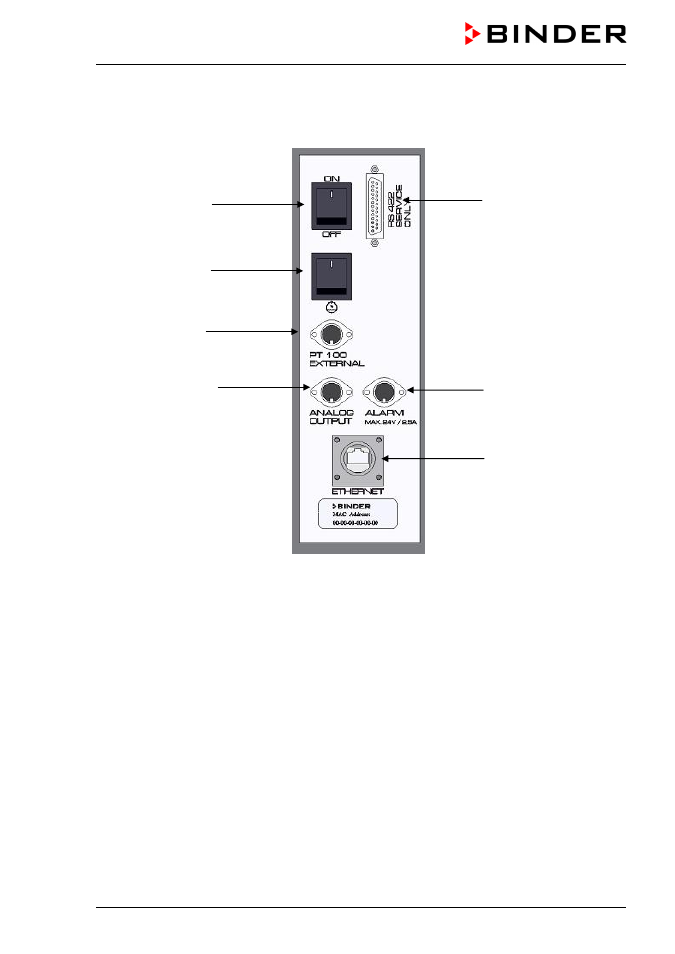
Figure 5: Lateral control panel KBF LQC at the right side of the humidity module
with options analog outputs, alarm contact, and additional Pt100 sensor
(3) Main power switch ON/OFF
(4) Humidity switch ON/OFF
(5) DIN-socket additional Pt100 temperature sensor (option)
(6) DIN-socket analog outputs (option)
(7) DIN-socket alarm contact (option)
(8) Ethernet interface for computer communication with indication of the MAC address
(9) RS422 interface (for service purpose only)
Advertising
This manual is related to the following products: