Humidity system, Ab c – BINDER KBF LQC 240 User Manual
Page 71
KBF LQC (E5.3) 07/2014
page 71/114
13. Humidity system
The humidity system is turned on with humidity switch (4) located in the right lateral control panel.
The constant climate chamber KBF LQC is equipped with a capacitive humidity sensor. This results in a
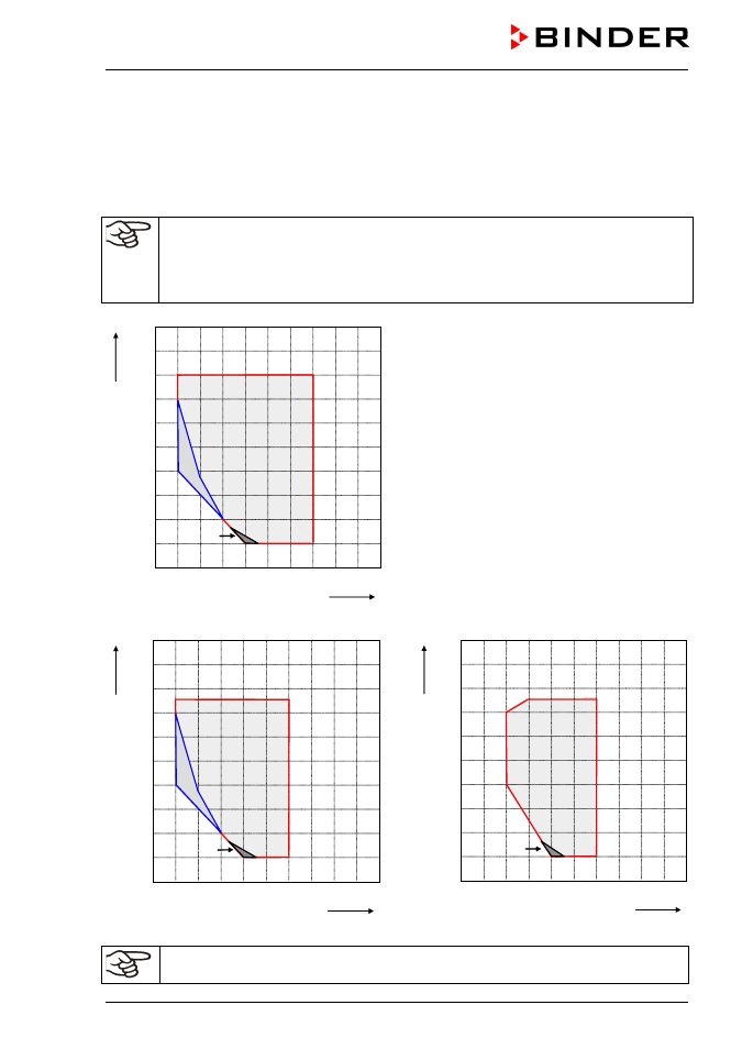
control accuracy of up to ± 3 % r.H. of the set point. The temperature-humidity diagrams (Figure 22) show
the possible working ranges for humidity.
The preset temperature and humidity values should be situated within the optimum range
(hatched range in Figure 22).Only within this area can the unit will not be exposed to excessive
moisture due to condensation.
In the short-term set points outside the optimum range can also be targeted. The control accu-
racies of ± 3 % r.H., however, cannot be guaranteed in this case.
0
10
20
30
40
50
60
70
80
90
100
10
20
30
40
50
60
70
80
90
100
% r.H.
°C
A
B
C
Figure 22: Temperature-Humidity diagrams
Range A: Control range of temperature and relative
humidity
Range B: Discontinuous range (no continuous op-
eration)
Range C: In this range, deviations of the technical
data are possible
KBF LQC without light cassettes
0
10
20
30
40
50
60
70
80
90
100
10
20
30
40
50
60
70
80
90
100
% r.H.
°C
A
B
C
0
10
20
30
40
50
60
70
80
90
100
10
20
30
40
50
60
70
80
90
100
% r.H.
°C
A
C
KBF LQC 240 with illumination
KBF LQC 720 with illumination
Heat emission of electrical devices connected inside the chamber may modify the temperature
and humidity range.